Scales
Scales. It is impractical to draw buildings, plots of land, and large parts of buildings such as doors and windows to their full size.


Scales
E N D
Presentation Transcript
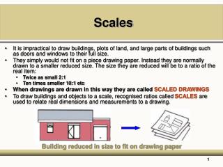
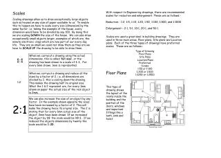
Scales • It is impractical to draw buildings, plots of land, and large parts of buildings such as doors and windows to their full size. • They simply would not fit on a piece drawing paper. Instead they are normally drawn to a smaller reduced size. The size they are reduced will be to a ratio of the real item: • Twice as small 2:1 • Ten times smaller 10:1 etc • When drawings are drawn in this way they are called SCALED DRAWINGS • To draw buildings and objects to a scale, recognised ratios called SCALESare used to relate real dimensions and measurements to a drawing. Building reduced in size to fit on drawing paper
Scales The main scales or ratios used in construction drawings are-:
Use of scales • The choice of scale will depend on two things: • The size of the object to be drawn • The amount of detail that needs to be shown • A scale is used to measure distances on drawings and for taking measurements of a drawing. 15.35 m • The distance shown above represents 15.35m it will be to a scale. • If scaled dimensions and written dimensions disagree, then the written dimension should always be used. • The scale shows how much smaller the plan or object is to its original size.
Use of scales • In a house drawing to a scale of 1:20 : • 1 mm will represent 20 mm • 2 mm will represent 40 mm • 10 mm will represent 200 mm • 100 mm will represent 2000 mm or 2 m • To a scale of 1: 10 100 mm will represent 1,000 mm or 1 m • To a scale of 1: 100 100 mm will represent 10,000 mm or 10 m • To a scale of 1: 50 100 mm will represent 5,000 mm or 5 m • To a scale of 1:5 250 mm will represent 1,250 mm or 1.250 m • To a scale of 1:200 150 mm will represent 30,000 mm or 30 m • It is simply a matter of multiplying the scale measurement by the scale ratio • 1: (10) x 100mm = 1000mm or 1m • 1: (50) x 100mm = 5000mm or 5m • 1: (200) x 150mm = 30,000mm or 30m
Student Activity • The drawing shows a ground floor plan of a small bungalow drawn to a scale of 1:100. • Using a scale rule complete the table by inserting all the required dimensions.
Student Activity • Complete the tables below by taking measurements from ground floor plan of bungalow
Student Activity • Insert the width of all the windows of the bungalow
Student Activity Scale Rule – Scale 1:100 • Mark on the scale rule the line representing 1.6m to a scale of 1:100
Student Activity Scale Rule – Scale 1:20 • Mark on the scale rule the line representing 1.7m to a scale of 1:20
Student Activity Scale Rule – Scale 1:50 • Mark on the scale rule the line representing 6m to a scale of 1:50
Student Activity Scale Rule – Scale 1:1250 • Mark on the scale rule the line representing 130m to a scale of 1:1250
350mm 600mm Drawing Lines Lines should be of THREE thicknesses 1. Thick 0.75 – 1mm thick for borders and drawing outlines 2. Medium 0.35 – 0.5mm thick ½ the thickness of the thick lines for hatching • Fine 0.2 – 0.25 mm thick ½ the thickness of the medium lines for dimension lines.
Dimension Lines • All drawings must be clear and accurate and easily understood by everyone who uses them. • In order to achieve this method of layout, symbols and abbreviations have been standardised ( See BS 1192 ). • Next slide are some examples of the most common different lines and what they represent on working drawings.
Dimension Lines • ThickMain outlines • MediumGeneral details and outlines • ThinConstruction and dimension Lines • Breakline Breaks in the continuity of a drawing • Thick chainPipe lines, drains and services • Thin chainCentre lines • Section line Showing the position of a section cut, the pointers show the direction of the view • Broken lineShows hidden details • Dimension line Indicates the distance between two points
1 2 3 4 5 6 7 8 9 UP Drawing Notation North Sign On site plans this sign shows the direction of true North. Stairs Arrow shows the direction of the steps and the number of steps in the stair.
Drawing Notation Windows A dotted line in the shape of a pointed arrow indicates the haging edge of a window sash Bottom hung Top hung Side hung
Running totals Dimension Lines • These should be thin lines, the ends can be shown in several ways • Open arrow head showing outside measurement • Closed arrow head showing inside measurement 350mm 0.5m 3500 2500 50 1000
Dimension Lines • Written dimension on horizontal lines should always be on top, preferably in the centre. • Written dimensions on vertical lines should be to the left and preferably in the centre. • All dimensions should be read from the bottom right hand corner.
Symbols • Symbols are graphical illustrations, which are used to represent the different building materials and components in a building drawing. • It was the custom to colour drawings, particularly the drawings submitted to the local authority for planning permission. • Sadly the practice is rarely used as it is slow and time consuming. • However is still the custom to colour in the position of a building in a block plan to show the position of the building and its surrounding boundaries. • Next slide are some of the most common symbols used and what they represent.
Lettering Drawings • The majority of drawings will require lettering and numbering. • This may vary from very little or none on a design to a great deal of production drawings and schedules. • Various techniques can be used, their application depending upon the type of drawing and its use. • The quickest method is by hand and it is important to develop a neat and accurate style from the beginning. • Poor lettering can ruin an otherwise good drawing. • Any lettering that is used, whether for notes, titles or headings, must be clear and easy to read. • Good use of lettering will not only give information but can improve the presentation of the drawing. • Faint guide lines could be drawn to help you practice the letters and numbers.
Lettering Drawings A B C D E F G H I J K L M N O P Q R S T U V W X Y Z 1 2 3 4 5 6 7 8 9 10 11 • The size of the letters depends on the size of the drawing paper. • For A1, A2 and A3 sized paper, the letters should be between 7 mm and 4 mm. • For A4 sized paper the letters should be between 5 mm and 3 mm
Title Panels • The British Standard 1192 sets the following recommendations. • Job Title and number • Name and Address of issuing firm or practice • Description of the drawing • Scale • Date the drawing was completed • Author of drawing • Checker of the drawing • Drawing number • Many construction firms have their drawing paper pre-printed with a title panel. • The panel should be at the bottom right hand corner of the drawing.
Title Panels Title Panels J & M Builders Drawing No 235 W R Smith 10 Greenways Greenham Scale 1:100 March 2003 Drawn CPR
Abbreviations • Abbreviations are a simple way of conveying information on drawings, reducing words to first letters, e.g. rain water pipe becomes R.W.P. • They allow the maximum information to be included on the drawing in a concise way. • Abbreviations have to be used in context e.g. MS stands for Mild Steel in the context of construction but it could also be an abbreviation for some other word in another situation. • Avoid making up your own abbreviations as these can lead to confusion.
Aggregate agg Air brick Ab Aluminium al Asbestos asb Asphalt asph Bitumen bit Boarding bdg Brickwork bwk BS Beam BSB Building bldg Cast iron CI Cement ct Column col Concrete conc Copper cu Damp proof course dpc Discharge pipe DP Foundation fdn Hardcore hc Hardboard hdbd Hardwood hwd Inspection chamber IC Insulation insul Tongued and grooved t&g Joist jst Plasterboard pbd Reinforced conc RC Abbreviations
Graphical Symbols • These are small standard pictures used to reduce the amount of drawing detail required on individual drawings. • Abbreviations and graphical symbols are often used together to give complete information.
Representation of components - fittings Sink Bath Cold water Cistern Hot water Cylinder Bidet Toilet Stop valve Hot & Cold Water drain off Drain or Sewer Flow Foul water Rain water head Surface water Rainwater outlet Gulley Radiator Cooker Towel rail Boiler Pump