MAC Simulation Results and Methodology
200 likes | 405 Vues
MAC Simulation Results and Methodology. Date: 2010-05-02. Proposal overview. This presentation is part and in support of the complete proposal described in 802.11-10/432r0 (slides) and 802.11-10/433r0 (text) that: Supports data transmission rates up to 7 Gbps

MAC Simulation Results and Methodology
E N D
Presentation Transcript
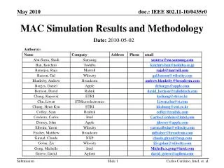
MAC Simulation Results and Methodology Date: 2010-05-02 Carlos Cordeiro, Intel, et. al.
Proposal overview • This presentation is part and in support of the complete proposal described in 802.11-10/432r0 (slides) and 802.11-10/433r0 (text) that: • Supports data transmission rates up to 7 Gbps • Supplements and extends the 802.11 MAC and is backward compatible with the IEEE 802.11 standard • Enables both the low power and the high performance devices, guaranteeing interoperability and communication at gigabit rates • Supports beamforming, enabling robust communication at distances beyond 10 meters • Supports GCMP security and advanced power management • Supports coexistence with other 60GHz systems • Supports fast session transfer among 2.4GHz, 5GHz and 60GHz Carlos Cordeiro, Intel, et. al.
Scope of this presentation This presentation As shown in this presentation, all TGad performance requirements have been met and all needed performance results delivered Carlos Cordeiro, Intel, et. al.
Antenna model and PHY abstraction • The Antenna/RF model of this simulator is the same as in 802.11-09/559r0 • The simulator implements a partition-based path loss model with ray-tracing (as in 802.11-09/782r0) • Other channel model parameters follow 802.11-09/334r7 • PHY: • Square array antenna • TX_Power: 10dBm output power • PHY rate is fixed (i.e., no real time link-adaptation) and is specified for each scenario • Used BER vs. SNR curves shown in 802.11-10/432r0 Carlos Cordeiro, Intel, et. al.
MAC and scheduler model • MAC • 16msec beacon interval • Every other BI includes a BT and an A-BFT • Every BI includes an AT • Allocation of SPs and CBPs depend upon the simulation scenario • SP for isochronous traffic • CBP for asynchronous traffic • Implements A-MPDU aggregation and Block Ack • Scheduler • Details described together with each simulation result (later slides) • For SP allocation, STAs send ADDTS Request frames to the PCP/AP which allocates SP for communication • For CBP, STAs send frames without prior reservation Carlos Cordeiro, Intel, et. al.
mSTA1 AP/PCP Point-to-point link FR Section 2.1.1 (1 Gbps at MAC SAP – Req01) (1/2) mSTA2 • The scenario is shown in the right • AP/PCP is located at (50,50) • mSTA1 is located in (51.5, 50.5) • mSTA2 is located in (50.5, 51.5) • Parameters as defined in 802.11-09/296r16 • mSTA1 is the source and has infinite buffer and has packets to send always • mSTA2 is the destination and all packets from mSTA1 are destined to mSTA2 • Higher layer protocol is UDP • All MSDU sizes are 8000 bytes • PHY rate = 6,756.75 Mbps (OFDM) and LOS channel Carlos Cordeiro, Intel, et. al.
Point-to-point link FR Section 2.1.1 (1 Gbps at MAC SAP – Req01) (2/2) • Additional assumptions • AP/PCP issues beacon every 16ms • All simulations start at 0 sec and end at 1 sec and use CBP with TXOP size to fit 2, 4 and 8 MSDUs with immediate ACK • CBP parameters: CWmin=3, Cwmax =7 • Summary of Results (last column is for SP) Carlos Cordeiro, Intel, et. al.
Link budget parameters for FR Section 2.1.2 (range requirement – Req03) (1/2) • Range test case as defined in 802.11-09/296r16 • Scenario has a single flow between a pair of stations (STA1 and STA 2) that are 10 meters apart • PHY assumptions • PHY rate of 2.079 Gbps used for directed data transmission • PHY rate of 1.386 Gbps used for directed ACK transmission • PHY rate of 1.386 Gbps used for directed control/mngt transmissions • mmWave Beacon is transmitted at Control MCS rate • Additional parameters • Offered load is set to 3Gbps Carlos Cordeiro, Intel, et. al.
Link budget parameters for FR Section 2.1.2 (range requirement – Req03) (2/2) Summary of results: Carlos Cordeiro, Intel, et. al.
Home living room (1/4) • Home living room scenario as defined in 802.11-09/296r16 • Scenario has a single flow • Antenna assumptions • STB (PCP/AP): 36 antenna elements • TV (STA): 36 antenna elements • Antenna element peak gain: 3dBi • Antenna arrays facing the ceiling • PHY assumptions • PHY rate of 4.158 Gbps used for directed data transmission • PHY rate of 2.772 Gbps used for directed ACK transmission • PHY rate of 1.386 Gbps used for directed control/mngt transmissions • mmWave Beacon is transmitted at Control MCS rate • Physical distance between TV and STB: 3.5 meters • Communication happens using reflection on ceiling Carlos Cordeiro, Intel, et. al.
Home living room (2/4) • Summary of results: Number of retries: 7 Carlos Cordeiro, Intel, et. al.
Home living room (3/4) Goodput at TV SNR at TV Carlos Cordeiro, Intel, et. al.
Home living room (4/4) ETE delay at TV Average ETE delay at TV Carlos Cordeiro, Intel, et. al.
Office conference room (1/4) • Office conference room scenario as defined in 802.11-09/296r16 • Scenario has 10 logical flows • Human body blockage and 2nd order reflection implemented as specified in 802.11-09/296r16 • HTTP request inter-arrival time was changed from 30sec to 1sec to increase the load, otherwise it becomes imperceptible • Antenna assumptions • STA2 and STA8 have 4 antenna elements • Remaining STAs have 36 antenna elements • Peak antenna element gain: 3dBi • PHY assumptions • PHY rate of 4.158 Gbps used for directed data transmission • PHY rate of 2.772 Gbps used for directed ACK transmission • PHY rate of 1.386 Gbps used for directed control/mngt transmissions • mmWave Beacon is transmitted at Control MCS rate Carlos Cordeiro, Intel, et. al.
Office conference room (2/4) • Summary of results: Number of retries: 7 Carlos Cordeiro, Intel, et. al.
Office conference room (3/4) File transfer goodput between AP/PCP and STA2 Aggregate goodput in the BSS Carlos Cordeiro, Intel, et. al.
Office conference room (4/4) Goodput of video streaming between STA2 and STA1 ETE delay of video streaming between STA2 and STA1 Carlos Cordeiro, Intel, et. al.