Simulation Study of Cu-Ag System Using Embedded-Atom Methodology
This study explores the Cu-Ag system using an embedded-atom potential. A simulation block composed of Cu and Ag crystals is analyzed under various conditions. The relaxation process, slip studies at different velocities, stress tensor calculation, interface structure examination, and tip displacements are investigated. The geometric registry at the interface, atomic registry, contact area, and lattices mismatch dislocations are also discussed. The study employs the common-neighbor analysis method.

Simulation Study of Cu-Ag System Using Embedded-Atom Methodology
E N D
Presentation Transcript
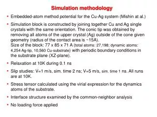
Simulation methodology • Embedded-atom method potential for the Cu-Ag system (Mishin at al.) • Simulation block is constructed by joining together Cu and Ag single crystals with the same orientation. The conic tip was obtained by removing all atoms of the upper crystal (Ag) outside of the cone given geometry (radius of the contact area is ~15A). Size of the block: 77 x 85 x 71 A (total atoms: 27,198; dynamic atoms: 4,254 Ag-tip, 10,560 Cu-substrate) with periodic boundary conditions in the substrate plane (XZ-plane). • Relaxation at 10K during 0.1 ns • Slip studies: V=1 m/s, sim. time 2 ns; V=5 m/s, sim. time 1 ns. All runs are at 10K. • Stress tensor calculated using the virial expression for the dynamics atoms of the substrate. • Interface structure examined by the common-neighbor analysis • No loading force applied
Y (1 1 1) X (1 0 -1) Z (1 -2 1) V Ag (fixed) Ag (dynamic) Cu (dynamic) Cu (fixed)
Actual tip displacements vs. imposed tip displacement Actual tip displacements are calculated as the displacement of the “center of mass” of atoms of the bottom layer of the tip Slip?
Stresses in the tip Stresses are calculated using the standard virial expression over all dynamic atoms of the tip Shear components Normal components
Displacements of the tip and shear stresses “1” “0” “1” “0”
Geometric registry at the tip (Ag) – substrate (Cu) interface XY-projection Ag A FCC stackingsequence in Ag B C Top layer ofthe substrate Cu Y (1 1 1) X (1 0 -1) Z (1 -2 1)
X (1 0 -1) Z (1 -2 1) Atomic registry at the tip (Ag) – substrate (Cu) interface FCC registry Black triangles shoe groups of atoms of the substrate,which are in FCC registry (ABC) with the atoms of the tip. Only the atoms of the top layer of the substrate (golden)and A-layer of the tip (blue) are shown. HCP registry Red triangles shoe groups of atoms of the substrate,which are in HCP registry (BC) with the atoms of the tip. Only the atoms of the top layer of the substrate (golden)and B-layer of the tip (blue) are shown. Contact area
X (1 0 -1) Z (1 -2 1) Atomic registry at the tip (Ag) – substrate (Cu) interface. Contd. Only the top layer of the substrate (golden atoms) is shown. Atomic rows of the substratewhich are not inregistry with the tip Lattices mismatchdislocations We do not need to create them.They pre-exist due to latticemismatch between Ag and Cu. FCC HCP FCC FCC HCP HCP
Atomic registry at the tip (Ag) – substrate (Cu) interface. Common-neighbors analysis http://www.physics.gmu.edu/~vivanov/afm/cuag/movies/agcu_1ms_2ns_10K_noforce.mpeg “0” HCP “1”