Download
1 / 29
310 likes | 461 Vues
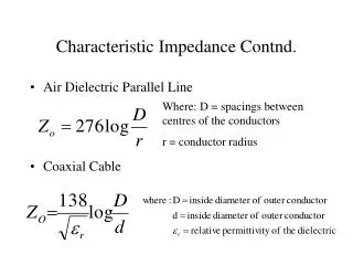
Lecture 11 Characteristic impedance and reflections. Impedances of terminated lines Voltage Standing Wave Ratio (VSWR) Voltage Standing Wave measurement. IMPEDANCES OF TERMINATED LINES. In this section we want to find an expression for the impedance of a load and line combination:.

E N D
Lecture 11Characteristic impedance and reflections • Impedances of terminated lines • Voltage Standing Wave Ratio (VSWR) • Voltage Standing Wave measurement
IMPEDANCES OF TERMINATED LINES In this section we want to find an expression for the impedance of a load and line combination: Zin = ? Zo ZL • For a transmission line with a mismatched load (i.e. with ZL ≠Zo) there will be reflected current and voltage waves as well as the forward waves. • The impedance of the load and line combination as seen by the source will be the ratio of VT/IT at the input terminals of the line: Zin = VT/IT = (V+ + V-)/(I+ - I-) (at the input end)
Zin = VT/IT = (V+ + V-)/(I+ - I-) (at the input end) So Zin will depend on the magnitude and phase of the reflected waves (V-, I-) when they reach the source, which will depend on… • how much of the incident waves (V+, I+) are reflected by the load • and on the phase change introduced by the reflection process i.e. it will depend on r • It will also depend on the length of the line (e.g. phase change over length l is bl )
I I+ I- Zin = V/I V V+ Zo V- ZL x = -l x = 0 Take the load to be at x = 0 and the input to be at x = -l (this allows the forward wave to propagate in the +ve x direction). VT = V+ + V- = Vi e-gxejwt + Vr e+gxejwt => VT = Vi e-gxejwt + rVi e+gxejwt (since Vr / Vi = r) Hence the voltage at the input end of the line (i.e. at x = -l ) is: V-l = Viejwt (egl+ re-gl)
V-l = Viejwt(egl + re-gl ) Similarly, the total current at any point on the line will be: IT = I+ - I- = Ii e-gx ejwt - Ire+gxejwt => IT = (Vi/Zo) e-gxejwt - (Vr/Zo) e+gx ejwt = (Vi/Zo) e-gxejwt - r(Vi/Zo) e+gx ejwt (since Vr / Vi = r) Hence the current at the input end of the line (i.e. at x = -l ) is: I-l = (Vi/Zo) ejwt(egl- re-gl )
Suppose we are dealing with a matched load… …for a matched load, r = 0, hence: I+ Zin = Zo V+ Zo Zo x = -l x = 0
Because of the relations between the hyperbolic functions [sinh(x), cosh(x) and tanh(x)] and the exponential function we can write the expression for Zin in two other equivalent forms. Using these relationships and the equation relating the voltage reflection coefficient to ZL and Zo
…. we can express Zin as: or: Original expression: All three expressions are equivalent – which one you use depends on whether you know ZL or ρ.
In the case of a lossless line a = 0, so g = a + jb = jb and is purely imaginary, so the hyperbolic functions reduce to trigonometric functions: Zin becomes: or: Original expression:
Example 5.1 - Impedance of a load and line combination. A 1m long, air-spaced transmission line with Zo = 50Wis terminated by a load of 40W. Calculate the input impedance, Zin, of the combined load and line at frequencies of 30 MHz, 75 MHz and 300 MHz, assuming the line is lossless.
3. N.B. Zo is NOT the impedance you would measure simply by connecting the line to an impedance measuring system – this would give you the open-circuit impedance Zoc. We will see later (Example 5.2) that Zo = (ZocZsc)1/2 where Zsc is the short-circuit impedance.
Example 5.2 - Characteristic impedance in terms of the open-circuit and short-circuit impedances. Find an expression relating the characteristic impedance Zo to the open-circuit and short-circuit impedances (Zoc, Zsc) of a transmission line.
The instantaneous TOTAL voltage will be the sum of the incident and reflected voltage waves at that instant. Incident voltage wave Reflected voltage wave Short circuit load
This link runs the Animation Standing_waves_x
The instantaneous TOTAL voltage is the sum of the incident and reflected voltage waves at that instant. Short circuit load
The instantaneous TOTAL voltage is the sum of the incident and reflected voltage waves at that instant. Short circuit load
Instantaneous total voltage Reflected wave voltage Incident wave voltage Extreme 1 Cancellation Extreme 2 reflected waveincident wave Instantaneous total voltage Reflected wave voltage Incident wave voltage Instantaneous total voltage Reflected wave voltage Incident wave voltage
The instantaneous TOTAL voltage is the sum of the incident and reflected voltage waves at that instant. VOLTAGE STANDING WAVE Short circuit load
The instantaneous TOTAL voltage is the sum of the incident and reflected voltage waves at that instant. VOLTAGE STANDING WAVE Short circuit load
Voltage envelope = standing wave t = time t = t1 t = t2 t = t3 Vr = Vi x |V| minimum (|V|=0) |V| maximum The standing wave shows how the AMPLITUDE, |V|, of the oscillations in the total voltage varies with distance, x.
Voltage envelope = standing wave Vr < Vi t = time t = t1 t = t2 t = t3 x |V| minimum If the reflected wave has a smaller amplitude than the incident wave, complete cancellation cannot occur - the standing wave does not drop to zero at the minima.
Summary q The impedance of a load and line combination is given by: or: or:
q For a lossless line the hyperbolic functions can be replaced by trigonometric functions: or: or:
Incident and reflected voltage waves superimpose and give rise to a regular variation in the voltage amplitude with distance along the line, i.e. they give rise to VOLTAGE STANDING WAVES. (The same is also true of the current.) Vr < Vi
Summary q The impedance of a load and line combination is given by: or: or:
q For a lossless line the hyperbolic functions can be replaced by trigonometric functions: or: or: