Lecture 4 Antenna Impedance Matching
810 likes | 2.13k Vues
Lecture 4 Antenna Impedance Matching. Dr. Hussein Attia Zagazig University. Ch. (9) in the textbook of (Antenna Theory, 3 rd Edition) C. A. Balanis Page 523. Typical Transmitter/Receiver Configuration. Antenna Impedance Matching.

Lecture 4 Antenna Impedance Matching
E N D
Presentation Transcript
Lecture 4Antenna Impedance Matching Dr. Hussein Attia Zagazig University Ch. (9) in the textbook of (Antenna Theory, 3rd Edition) C. A. Balanis Page 523
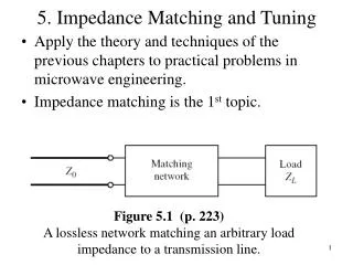
Antenna Impedance Matching To maximize power transfer from the transmitter to the antenna or from the receiving antenna to the receiver front end, the impedance of the antenna should be matched to the characteristic impedance of the interconnecting transmission line. This is usually realized by an impedance matching network placed between the antenna and the feed line.
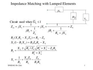
Antenna Impedance Matching There are many circuit configurations that could be used for this purpose. Two narrowband designs are presented below. 1- Sub-Matching Ideal matching at a given frequency can be accomplished by placing a short- or open-circuited shunt stub a distance s1from the transmission-line–antenna element connection, as shown in Figure. Steps of design Assuming a real characteristic impedance (ZC), the length s1is chosen so as to make the real part of the antenna element impedance equal to the characteristic impedance (ZC). The length s2of the shunt line is varied until the susceptance*of the stub (Y”in) is equal in magnitude but opposite in phase to the line input susceptance at the point of the transmission line–shunt element connection. The matching procedure is illustrated best graphically with the use of a Smith chart. short-circuited shunt stub * susceptanceis the imaginary part of admittance
Antenna Impedance Matching 2- Quarter-Wavelength λ/4 Transformer • Another technique that can be used to match the antenna to the transmission line is to use a λ/4 transformer. • If the input impedance of the antenna is real, the transformer is attached directly to the antenna. • However if the antenna impedance is complex, the transformer is placed a distance s1away from the antenna, as shown in Figure. • The distance s1 is chosen so that the input impedance toward the load at s1is realand designated as R1. • To provide a match, the transformer characteristic impedance ZC1 should be , where ZCis the characteristic impedance (real) of the input transmission line.
Balun (Balanced line to unbalanced line transformer)
“Balun” (Balanced line to unbalanced line transformer) Balanced System • In case the antenna is being fed by a two-wire transmission line (two parallel-conductor line) as shown. • The twin-lead (two-wire) transmission line is a symmetricalline. • The two lines are coupled to the antenna in the same way. • So, they provide a balancedsystem.
“Balun” (Balanced line to unbalanced line transformer) Unbalanced System • In case the antenna is being fed by a coaxial line as shown. • The inner and outer conductors of the coaxial line are not coupled to the symmetrical arms of the dipole in a similar manner. So, they provide the unbalance. unbalanced coaxial line • This excites a current on the exterior surface of the outer conductor (I3). This current has undesirable effects on the radiation and the input impedance of the antenna. This is shown in Figure above where an electrical equivalent circuit is also indicated. • The amount of current flow I3on the outside surface of the outer conductor is determined by the impedance Z from the outer shield to ground. If Zcan be made very large, I3 can be reduced significantly. Devices that can be used to balance inherently unbalanced systems, by canceling or choking the outside current, are known as baluns (balance to unbalance).
“Balun” (Balanced line to unbalanced line transformer) “Balun” is used to eliminate I3. Several types of baluns are shown below. • One type of a balun is that shown in Figure, referred to usually as a bazooka balun. • Mechanically it requires that a λ/4 in length metal sleeve, and shorted at its one end, encapsulates the coaxial line. • Electrically the input impedance at the open end of this λ/4 shorted transmission line, which is equivalent to Zg, will be very large (ideally infinity). Thus the current I3 will be choked, if not completely eliminated, • Hence, The system will be nearly balanced.
“Balun” (Balanced line to unbalanced line transformer) • This kind of Balun is called (Coaxial Balun) • The outsidemetal conductor of the coaxial line is split and a portion of it is removedon opposite sides. • The remainingopposite parts of the outer conductor represent electrically a two shorted λ/4 • parallel transmission lines. Hence, it will work in a similar manner to bazooka balun. • All of the baluns discussed here are narrowband devices.
Folded Dipole • To achieve good directional pattern characteristics and at the same time provide good matchingto practical coaxial lines with 50- or 75-ohm characteristic impedances, the length of a single wire element is usually chosen to be λ/4 ≤ l < λ. • The most widely used dipole is that whose overall length is l ≈λ/2, and which has an input impedance of Zin≈ 73 + j42.5 and directivity of D0 ≈≈1.643. • In practice, there are other very common transmission lines whose characteristic impedance is much higher than 50 or 75 ohms. • For example, a “twin-lead” transmission line (usually two parallel wires) embedded in a low-loss plastic material used for support and spacing) is widely used for TV applications and has a characteristic impedance of about 300 ohms. • In order to provide good matching characteristics, variations of the single dipole element must be used. One simple geometry that can achieve this is a folded wire which forms a very thin (s << λ) rectangular loop as shown in Figure.
Folded Dipole It is required to calculate the input admittance of the folded dipole antenna A simple analysis method for folded dipoles is outlined below, the folded dipole antenna is divided into two separate circuits. If the corresponding branches of the two circuits are added, it will produce the original folded dipole antenna.
Folded Dipole (1) From (1) and (2) (2) Input admittance of folded dipole Input admittance of short-circuited T.L
Folded Dipole Input admittance of folded dipole then • The impedance of the folded dipole is four times greater than that of an isolated dipole of the same length as one of its sides. If l = λo/2 then