Impedance Matching in Loaded Q Circuits
640 likes | 938 Vues
Learn how the loaded Q of a resonant circuit is affected by source and load resistances, and how to achieve maximum power transfer by impedance matching. Explore L-network analysis, complex impedance handling, absorption, and resonance techniques, with practical examples.

Impedance Matching in Loaded Q Circuits
E N D
Presentation Transcript
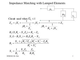
LOADED Q • The Q of a resonant circuit was defined to be equal to theratio of the center frequency of the circuit to its 3-dB bandwidth • The loaded Q of a resonant circuit is dependent uponthree main factors. 1. The source resistance (Rs). 2. The load resistance (RL). 3. The component Q as defined previous.
The effect of Rs and RL on loaded Q Rs = 50 Rs = 1000
Maximum Power Transfer In DC circuits, maximum power will be transferred from a source to its load if the load resistance equals the source resistance
Maximum Power Transfer The source (Zs), with a series reactive component of +jX (an inductor), is driving its complex conjugate load impedance consisting of a −jX reactance (capacitor) in series with RL. The +jX component of the source and the−jX component of the load are in series and, thus,cancel each other, leaving only Rs and RL, which are equal by definition. Since Rs and RL are equal, maximum power transfer
Simple Black Box Analysis • Source 100-ohm • Load 1000-ohm • So, in this situation • The available power from source would be lost about 4.8 dB To maximum power transfer This is done by forcing the 100-ohm source to see 100 ohmswhen it looks into the impedance-matching network. But how?
First Step. • Simple place -j333-ohm capacitor is placed across the 1000-ohm load resistor • So we have
Impledance.. • Nowthat we have an apparent series 100−j300-ohm impedancefor a load,
To match the impledance • All we must do to complete the impedance match tothe 100-ohm source is to add an equal and opposite (+j300 ohm)reactance in series
Summary • The function of the shuntcomponent of theimpedance-matching network is to transform a larger impedancedownto a smaller value with a real part equal to the real part of theother terminating impedance (in our case, the 100-ohm source). • The series impedance-matching element then resonates with orcancels any reactive component present, thus leaving the sourcedriving an apparently equal load for optimum power transfer.
Equation for design of the impedance-matching The quantities Xp and Xs may be either capacitive or inductivereactance but each must be of the opposite type. Once Xp ischosen as a capacitor, for example, Xs must be an inductor, andvice versa.
Example 1 • Design a circuit to match a 100-ohm source to a1000-ohm load at 100 MHz. Assume that a DC voltagemust also be transferred from the source to the load. The need for a DC path between the source and loaddictates the need for an inductor in the series leg,
Solution (con’t) Final circuit
DEALING WITH COMPLEX LOADS • Real world input/output impledance Transmission lines, mixers, antennas, transistor and most other sources
Two Basic Approaches in Handling Complex Impedances • Absorption • To actually absorb any stray reactances intothe impedance-matching network itself. • This can be donethrough prudent placement of each matching elementsuch that element capacitors are placed in parallel withstray capacitances, and element inductors are placed inseries with any stray inductances.
Two Basic Approaches in Handling Complex Impedances • Resonance • To resonate any stray reactance with anequal and opposite reactance at the frequency of interest. • Once this is done the matching network design canproceed as shown for two pure resistances in Example 1.
Example 2 • Use the absorption approach to match the source and load shown below (at 100 MHz).
Solution • The first step in the design process is to totally ignore the reactances and simply match the 100-ohm real part of the source to the 1000-ohm real part of the load (at 100 MHz) • Goal
Example 3 • Design an impedance matching network that will block the flow of DC from the source to the load in Fig. The frequency of operation is 75 MHz. Try the resonant approach.
Solution • The need to block the flow of DC from the source to the load dictates the use of the matching network
first, let’s get rid of the stray 40-pF capacitor by resonating it with a shunt inductor at 75 MHz.
Now that we have eliminated the stray capacitance, we can proceed with matching the network between the 50-ohm load and the apparent 600-ohm load
THREE-ELEMENT MATCHING The three-element T network The three-element Pi network.
The Pi Network • The Pi network can best be described as two “back-to-back” L networks that are both configured to match the load and the source to an invisible or “virtual” resistance located at the junction between the two networks.
The significance of the negative signs for −Xs1 and−Xs2 is symbolic. • They are used merely to indicate that the Xs values are the opposite type of reactance from Xp1 and Xp2, respectively. • Thus, if Xp1 is a capacitor, Xs1 must be an inductor, and vice versa. Similarly, if Xp2 is an inductor, Xs2 must be a capacitor, and vice versa. They do not indicate negative reactances (capacitors). • Now, we have
Example 4 • Using Figure below as a reference, design four different Pi networks to match a 100-ohm source to a 1000-ohm load. Each network must have a loaded Q of 15.
Solution • From
The Q for the other L network is now defined by the ratio of Rs to R • Notice here that the source resistor is now considered to be in the shunt leg of the L network. Therefore, Rs is defined as Rp, and
Remember that the virtual resistor (R) is not really in the circuit and, therefore, is not shown. Reactances −Xs1 and −Xs2 are now in series and can simply be added together to form a single component.
The only constraint is that Xp1 and Xs1 are of opposite types, and Xp2 and Xs2 are of opposite types. • Therefore, to perform the transformation from the dual-L to the Pi network, the two series components are merely added if they are alike, and subtracted if the reactances are of opposite type.
Which one to choose? • Depend on any number of factors including: 1. The elimination of stray reactances. 2. The need for harmonic filtering. 3. The need to pass or block DC voltage.
The T network • The design of the 3-element T network is exactly the same as for the Pi network except that with the T, you match the load and the source, through two L-type networks, to a virtual resistance that is larger than either the load or source resistance. This means that the two L-type networks will then have their shunt legs connected together
Q value of T • since we have reversed or “flip-flopped” the L sections to produce the T network, we must also make sure that we redefine the Q formula to account for the new resistor placement, in relation to those L networks.
Example 5 • Using Figure below as a reference, design four different networks to match a 10-ohm source to a 50-ohm load. Each network is to have a loaded Q of 10.
Solution • we can find the virtual resistance we need for the match • From previously, • Now, for the L network on the load end, the Q is defined by the virtual resistor and the load resistor. Thus,
THE SMITH CHART • The chart was originally conceived back in the 1930s by a Bell Laboratories engineer named Phillip Smith, who wanted an easier method of solving the tedious repetitive equations that often appear in RF theory
Smith Chart Construction • Step 1: The reflection coefficient of a load impedance when given a source impedance can be found by the formula: • In normalized form, this equation becomes: • where Zo is a complex impedance of the form R+jX
The polar form of the reflection coefficient can also be represented in rectangular coordinates: • So, we have • If we draw the family of curves we have:
Basic Smith Chart Tips: Important • All the circles have one same, unique intersecting point at the coordinate (1, 0). • The zero circle where there is no resistance (R=0) is the largest one. • The infinite resistor circle is reduced to one point at (1, 0). • There should be no negative resistance. If one (or more) should occur, you will be faced with the possibility of oscillatory conditions. • Another resistance value can be chosen by simply selecting another circle corresponding to the new value.
Plotting Impedance Values 1+j1 1-j1