Download

1 / 35
350 likes | 566 Vues
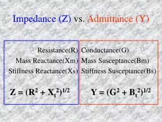
Impedance Matching (2). Outline. Three Element Matching Motivation Pi Network T Network Low Q or Wideband Matching Network Impedance Matching on Smith Chart Two-Element Three-Element Matching Multi-Element Matching Genesis. RV=4.424 Ohms. Component Q= 4.73. Circuit Q.

E N D
Outline • Three Element Matching • Motivation • Pi Network • T Network • Low Q or Wideband Matching Network • Impedance Matching on Smith Chart • Two-Element • Three-Element Matching • Multi-Element Matching • Genesis
RV=4.424 Ohms Component Q=4.73
Circuit Q Q of Vin/VS=102.2/(125.4-83.1)=2.416 Circuit Q is different from component Q! Q of Vout/VS=98/(117.6-73.4)=2.21
Four Combinations of L-Match RL>RS RS>RL
Virtual Resistor Virtual Resistance must be smaller than source resistance! (Blocks DC) RS>RL RL>RS
Design a Pi-Match • RS=100 Ohms • RL=1000 Ohms • Resonant Frequency: 100 MHz • Q2=15 • R2/R=(Q22+1)/(Q12+1) (See attached) Q1 Q2
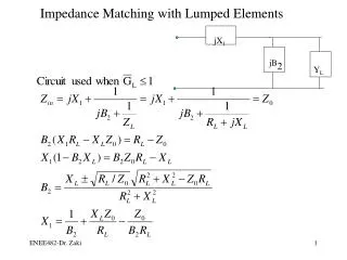
Calculation Design Sequence: Q1, Q2 RV L2, C2 L1, C1
T-Match RL>RS RS>RL
Schematic Q1=10 Q2=4.472 RV=1050 Ohms
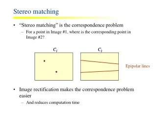
Review of Smith Chart • Adding an inductor in series • Adding a capacitor in series • Adding a capacitor in parallel • Adding an inductor in parallel
Adding an Inductor in Series Insertion of a series inductor to an impedance moves the impedance upward, causing a rotation clockwise along a constant circle of resistance
Adding a Capacitor in Series Insertion of a seriescapacitor to an impedance move impedance downward, causes a rotation counterclockwise along a constant circle of resistance
Adding a Shunt Capacitance Insertion of a shunt capacitor causes a rotation clockwise along a constant circle of admittance
Adding a Shunt Inductance Insertion of a shunt inductor causes a rotation counter clockwise along a constant circle of admittance
Example Design a matching network with a source impedance of 25+15j Ohm and output impedance of 100+25j Ohms.(We need to have match the source and load to their complex conjugates)
Starting Smith Chart (source) (load)
Four Combinations of L-Match (Series L causes clockwise Movement on constant R on smith chart… …) (The only one) RL>RS RS>RL
Constant Q Q of series impedance=ratio of reactance to resistance
Example 4-4 Constant Q of 15 Q=15 The end of large terminating resistor will determine the Q.
Example 4-4 (Adding a Series L) Get the admittance circuit with a series L
Example 4.4 Get back with the center of chart with a shunt cap.
Example 4.8 • Design a T network to match Z=15+15j Ohm source to a 225 Ohm load at 30 MHz with a loaded Q of 5.
Example 4.8 Get on Constant Q=5 curve