Impedance Matching (1)
670 likes | 1.3k Vues
Impedance Matching (1). Maximum Power Transfer. Choose an RL in order to maximize power delivered to RL. Power Delivered to the Load. Numerical Example. V TH =1 V R TH =50 Ω. Conclusion!. Maximum power is delivered to the load resistor when R L is equal to R TH.

Impedance Matching (1)
E N D
Presentation Transcript
Maximum Power Transfer Choose an RL in order to maximize power delivered to RL.
Numerical Example • VTH=1 V • RTH=50 Ω
Conclusion! • Maximum power is delivered to the load resistor when RL is equal to RTH.
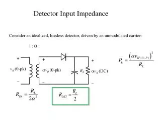
Max Power Transfer for Complex Source Impedance At resonant frequency, the series impedance of the inductor and capacitor is zero.
Summary RL>RS RS>RL
L Network • Different L netowrk • Difference bewteenhighpass and low pass • Examine butterworth filter from the point of view of matching….
Resistance Transformation RP must be larger than RS (See derivation in the handout)
High Pass Match Note: There is not a DC path to ZL. RS must be larger than RL! See derivation! QS=sqrt(RS/RL-1) QS=1/(ωRLC) QS=RS/(ωL)
Dealing With Complex Load • Absorption Approach • Resonance Technique
Match Via Absorption Approach • Ignore stray component • Match the load resistance to the source resistance with an L-match • Subtract the stray component from the L-match value
Account for Stray Components This technique will not work if the stray components is much larger than L match components. E.g. if 2pF is replaced by 6 pF, then this technique will not work.
Resonant Approach • Resonate any stray reactance with an equal and opposite reactance at the frequency of interest!
Example Resonate the 40 pF with a parallel L.
Intuition • If the Q is sufficiently large, LS≈LP and CS≈CP. • RP is Q2 times RS.
Summary RL>RS RS>RL
Smith Chart Construction (+) (-) (The center line represents an axis where X=0.)
Smith Chart Utility 1. Select Smith Chart Match Click on Tools, then select Smith chart utility 3. Select first option
Negative Capacitance! Negative capacitance
Add a Series Inductor (1) (2) Double click on the smith chart to drop the component
Adding an Inductor in Series Insertion of a series inductor to an impedance moves the impedance upward, causing a rotation clockwise along a constant circle of resistance
Series Inductance Low L High L Neg L fixed frequency Insertion of a series inductor to an impedance moves the impedance upward, causing a rotation clockwise along a constant circle of resistance
Adding a Capacitor in Series Insertion of a seriescapacitor to an impedance move impedance downward, causes a rotation counterclockwise along a constant circle of resistance
Series Capacitance Neg C High C Low L fixed frequency Insertion of a seriescapacitor to an impedance move impedance downward, causes a rotation counterclockwise along a constant circle of resistance