Detector Input Impedance
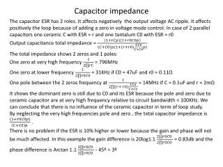
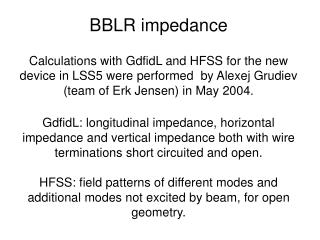
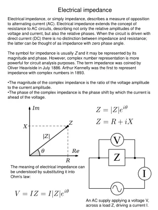
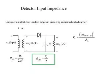
Detector Input Impedance. Consider an idealized, lossless detector, driven by an unmodulated carrier:. 1 : a. + v if (0-pk) _. + a v if (0-pk) _. + a v if (DC) _. R L. Minimum Power to the Detector.

Detector Input Impedance
E N D
Presentation Transcript
Detector Input Impedance Consider an idealized, lossless detector, driven by an unmodulated carrier: 1 : a + vif (0-pk) _ + avif (0-pk) _ + avif (DC) _ RL
Minimum Power to the Detector For a modulated signal, the the minimum peak AC voltage into the detector must exceed the diode turn-on voltage. If the carrier voltage coming out of the final IF amplifier is EC(0-pk), then aEC(1-m) > VD; or The minimum carrier power required is Note that the minimum total power required for undistorted output is not affected by the transformer turns ratio! The minimum total power into the detector must be:
Minimum Receiver Gain In terms of sideband power, The receiver should have sufficient total gain (GT) such that the signal out of the final IF amp will be sufficient to drive the detector without distortion whenever the signal level entering the antenna has sufficient power to make the detector output exceed the minimum required output SNR (12 dB for voice communication). This occurs when the sideband power entering the antenna is:
Minimum Receiver Gain (cont) Expressing PSB,DET in dB, we have: Note that the first term on the RHS only reflects detector parameters, and the second term reflects only modulation index. It is convenient to refer to the first term as “Reference Detector Power”, PDR(dBW), as it captures the two important detector parameters in one number. The minimum required total gain for the receiver is:
Receiver Sensitivity Receiver Sensitivity is a key specification which defines the minimum signal level required at the receiver input to produce a specified SNR at the detector (demodulator) output. It is usually expressed in dBf (femto-watts) or microvolts (RMS, 50 ohm source) . We have already determined the minimum sideband power required at the receiver input to produce a specified SNR , so total power required would be:
Example Example: An AM (m = 0.6) receiver has the following characteristics: B = 20 kHz Detector RL = 5000 W NF = 15 dB Detector VD = 0.2 V Threshold SNR = 12 dB SNR = 12 dB @ PANT = PSEN RF Front End IF Strip Detector PSB,ANT
Dynamic Range From an AC Load Line Analysis, we can determine the maximum 0-Pk amplitude of vIF < VIF(max). If we are dealing with a modulated AM signal, the maximum 0-Pk amplitude of vIF is EC(1+m)< VIF(max). We have previously determined that to avoid negative peak clipping, the minimum 0-Pk AC voltage into the detector must exceed the diode turn-on voltage: aEC(1-m) > VD .
Dynamic Range The ratio of maximum to minimum signal range for undistorted output is called “Dynamic Range”. Expressed in dB it is: Example: The final amplifier in the IF strip of our previous receiver will accommodate a maximum AC output of 6 volts 0-pk, and has an output impedance of 100 ohms. Since RDET = RL/2 = 2500 W, the transformer should have a = 5 to match the IF amp to the detector. For modulation index m = 0.6, the dynamic range is:
Automatic Gain Control The previous example uses reasonable numbers, and the result, 15.7 dB, is not a respectable value for dynamic range. If the radio’s maximum range is 50 miles, then the IF will clip at ranges less than 1.5 miles, and this would be unacceptable. The solution is to provide a means for reducing the gain of the receiver when the output signal begins to approach the clipping range. Since the detector output contains a DC level proportional to the received carrier level, this DC level can be extracted from the detector output using a low-pass filter, and fed back as a control voltage to reduce receiver gain.