Electrical impedance
Electrical impedance.

Electrical impedance
E N D
Presentation Transcript
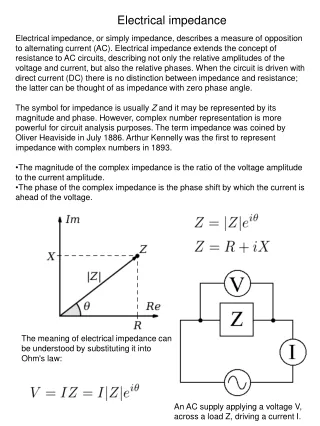
Electrical impedance • Electrical impedance, or simply impedance, describes a measure of opposition to alternating current (AC). Electrical impedance extends the concept of resistance to AC circuits, describing not only the relative amplitudes of the voltage and current, but also the relative phases. When the circuit is driven with direct current (DC) there is no distinction between impedance and resistance; the latter can be thought of as impedance with zero phase angle. • The symbol for impedance is usually Z and it may be represented by its magnitude and phase. However, complex number representation is more powerful for circuit analysis purposes. The term impedance was coined by Oliver Heaviside in July 1886. Arthur Kennelly was the first to represent impedance with complex numbers in 1893. • The magnitude of the complex impedance is the ratio of the voltage amplitude to the current amplitude. • The phase of the complex impedance is the phase shift by which the current is ahead of the voltage. The meaning of electrical impedance can be understood by substituting it into Ohm's law: An AC supply applying a voltage V, across a load Z, driving a current I.
The magnitude of the impedance acts just like resistance, giving the drop in voltage amplitude across an impedance for a given current . The phase factor tells us that the current lags the voltage by a phase of (i.e. in the time domain, the current signal is shifted to the right with respect to the voltage signal). Just as impedance extends Ohm's law to cover AC circuits, other results from DC circuit analysis can also be extended to AC circuits by replacing resistance with impedance. In order to simplify calculations, sinusoidal voltage and current waves are commonly represented as complex-valued functions of time: This representation using complex exponentials may be justified by noting that (by Euler's formula): i.e. a real-valued sinusoidal function (which may represent our voltage or current waveform) may be broken into two complex-valued functions. By the principle of superposition, we may analyze the behavior of the sinusoid on the left-hand side by analyzing the behavior of the two complex terms on the right-hand side. Given the symmetry, we only need to perform the analysis for one right-hand term; the results will be identical for the other. At the end of any calculation, we may return to real-valued sinusoids by further noting that In other words, we simply take the real part of the result.
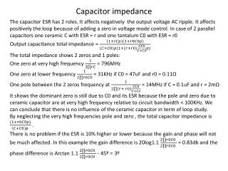
The impedance of an ideal resistor is purely real and is referred to as a resistive impedance: Ideal inductors and capacitors have a purely imaginary reactive impedance: Capacitive reactance Inductive reactance Combining impedances Series combination Parallel combination
LC circuit An LC circuit is a resonant circuit or tuned circuit that consists of an inductor L and a capacitor C. When connected together, an electric current can alternate between them at the circuit's resonant frequency. LC circuits are used either for generating signals at a particular frequency, or picking out a signal at a particular frequency from a more complex signal. They are key components in many applications such as oscillators, filters, tuners and frequency mixers. An LC circuit is an idealized model since it assumes there is no dissipation of energy due to resistance. The resonant frequency of the LC circuit.
Series LC circuit What happens when ?
Parallel LC circuit What happens when ?
RLC circuit Tuned circuits, such as this one, have many applications particularly for oscillating circuits and in radio and communication engineering. They can be used to select a certain narrow range of frequencies from the total spectrum of ambient radio waves. For example, AM/FM radios typically use an RLC circuit to tune a radio frequency. Most commonly a variable capacitor allows you to change the value of C in the circuit and tune to stations on different frequencies. Other practical designs vary the inductance L to adjust tuning.
An example of the application of resonant circuits is the selection of AM radio stations by the radio receiver. The selectivity of the tuning must be high enough to discriminate strongly against stations above and below in carrier frequency, but not so high as to discriminate against the "sidebands" created by the imposition of the signal by amplitude modulation.
What if there is no emf? attenuation a) damped oscillations b) overdamping, no oscillations