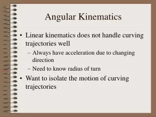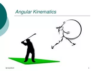
Angular Kinematics
Angular Kinematics. D. Gordon E. Robertson, PhD, FCSB School of Human Kinetics University of Ottawa. Angular Kinematics Differences vs. Linear Kinematics. Three acceptable SI units of measure revolutions (abbreviated r) degrees (deg or º, 360º = 1 r)

Angular Kinematics
E N D
Presentation Transcript
Angular Kinematics D. Gordon E. Robertson, PhD, FCSB School of Human Kinetics University of Ottawa
Angular KinematicsDifferences vs. Linear Kinematics • Three acceptable SIunits of measure • revolutions (abbreviated r) • degrees (deg or º, 360º = 1 r) • radians (rad, 2p rad = 1 r, 1 rad ≈ 57.3 deg) • Angles are discontinuous after one cycle • Common to use both absolute and relative frames of reference • In three dimensions angular displacements are not vectors because they do not add commutatively (i.e., a + b≠b + a) Biomechanics Lab, University of Ottawa
Absolute or Segment AnglesUses Newtonian or inertial frame of reference • Used to define angles ofsegments • Frame of reference is stationary with respect to the ground, i.e., fixed, not moving • In two-dimensional analyses, zero is a right, horizontal axis from the proximal end • Positive direction follows right-hand rule • Magnitudes range from 0 to 360 or 0 to +/–180 (preferably 0 to +/–180) deg Biomechanics Lab, University of Ottawa
Angle of Foot Biomechanics Lab, University of Ottawa
Angle of Leg Biomechanics Lab, University of Ottawa
Relative or Joint AnglesUses Cardinal or anatomical frame of reference • Used to define angles of joints, therefore easy to visualize and functional • Requires three or four markers or two absolute angles • Frame of reference is nonstationary, i.e., can be moving • “Origin” is arbitrary depends on system used, i.e., zero can mean “neutral” position (medical) or closed joint (biomechanical) Biomechanics Lab, University of Ottawa
Angle of Ankle Biomechanics Lab, University of Ottawa
Angle of Knee Biomechanics Lab, University of Ottawa
Absolute vs. Relative • knee angle = [thigh angle – leg angle] –180 =[–60–(–120)]–180 = –120 Biomechanics Lab, University of Ottawa
Joint Angles in 2D or 3D • q = cos–1[(a∙b)/ab] • a and b are vectors representing two segments • ab = product of segment lengths • a∙b= dot product Biomechanics Lab, University of Ottawa
Angular KinematicsFinite Difference Calculus • Assuming the data have beensmoothed, finite differences may be taken to determine velocity and acceleration. I.e., • Angular velocity • omegai = wi = (qi+1 – qi-1) / (2 Dt) • where Dt = time between adjacent samples • Angular acceleration: • alphai = ai = (wi+1 – wi-1) / Dt = (qi+2 –2qi +qi-2) / 4(Dt)2 • or ai = (qi+1 –2qi +qi-1) / (Dt)2 Biomechanics Lab, University of Ottawa
3D AnglesEuler Angles Ordered set of rotations: a, b, g Start with x, y, z axes rotate about z (a) to N rotate about N (b) to Z rotate about Z (g) to X Finishes as X, Y, Z axes Biomechanics Lab, University of Ottawa
Visual3D AnglesSegment Angles • Segment angle is angle of a segment relative to the laboratory coordinate system x, y, z vs. X, Y, Z • z-axis: longitudinal axis • y-axis: perpendicular to plane of joint markers (red) • x-axis: orthogonal to y-z plane Biomechanics Lab, University of Ottawa
Visual3D AnglesJoint Cardan Angles • Joint angleis the angle of a segment relative to a second segment x1, y1, z1 vs. x2, y2, z2 • order is x, y, z • x-axis: is flexion/extension • y-axis: is varus/valgus, abduction/adduction • z-axis: is internal/external rotation Biomechanics Lab, University of Ottawa
Computerize the Process • Visual3D, MATLAB, Vicon, or SIMI etc. Biomechanics Lab, University of Ottawa