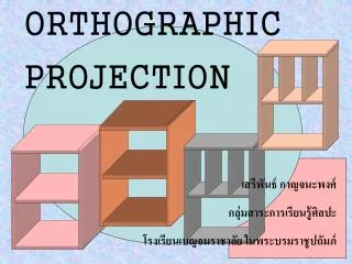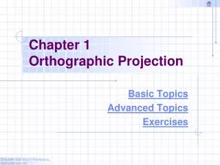
Chapter 4 Orthographic Writing
Chapter 4 Orthographic Writing. Views selection. Alignment of views. Orthographic writing steps. Basic dimensioning. Tangency and intersections. TOPICS. View Selection. VIEW SELECTION STEPS. 1. Orient the object to the best position relative to a glass box.

Chapter 4 Orthographic Writing
E N D
Presentation Transcript
Chapter 4 Orthographic Writing
Views selection Alignment of views Orthographic writing steps Basic dimensioning Tangency and intersections TOPICS
VIEW SELECTION STEPS 1. Orient the object to the best positionrelative to a glass box. 2. Select the front view. 3. Select adjacent views.
The object should be placed in its natural position. The object should presents its features in actualsize and shape in orthographic views. STEP 1 : Orient the Object GOOD NO !
The object’s longest dimension should be presented as a width. STEP 2 : Select a Front View First choice Second choice Waste more space Inappropriate GOOD
The adjacent views that are projected from the selected front view should appear in its natural position. STEP 2 : Select a Front View Inappropriate
Choose the view that have the fewest number ofhidden lines. STEP 2 : Select a Front View GOOD Inappropriate
Choose the view that have the fewest number ofhidden lines. STEP 3 : Select an Adjacent View GOOD Inappropriate GOOD Inappropriate
Choose the minimum number of views that can represent the major features of the object. STEP 3 : Select an Adjacent View Necessary Hole’s location can be specified on the same view. Easy to understand Difficult to interprete. Necessary
Choose the views that are suitable to a drawingspace. STEP 3 : Select an Adjacent View POOR Not enough space for dimensioning.
Choose the views that are suitable to a drawingspace. STEP 3 : Select an Adjacent View GOOD
D W H D W H Example: View selection mislead to… F.V. Three views F.V. & T.V. F.V. & R.S.V. Size description Shape description
Flat part having a uniform thickness. ONE-VIEW DRAWING 1 Thick These 2 views provide only informationabout the part thickness ! Unnecessary
Cylindrical-shaped part. ONE-VIEW DRAWING Unnecessary Repeat ! Infer from CL Unnecessary
There exists an identical view. TWO-VIEW DRAWING Repeat ! Unnecessary
The 3rd view has no significant contours of the object. TWO-VIEW DRAWING Unnecessary
The 3rd view has no significant contours of the object. TWO-VIEW DRAWING Unnecessary
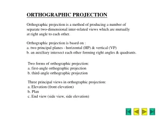
PROJECTION SYSTEMS 1. First angle system - European country- ISO standard First Quadrant 2. Third angle system - Canada, USA, Japan, Thailand Third Quadrant
ORTHOGRAPHIC PROJECTION 3rd angle system 1stangle system
ORTHOGRAPHIC VIEWS 3rd angle system 1stangle system Folding line Folding line Folding line Folding line
ORTHOGRAPHIC VIEWS 3rd angle system 1stangle system Top View Right Side View Front View Front View Right Side View Top View
PROJECTION SYMBOLS First angle system Third angle system
PROJECTION SYMBOLS Suggested proportion d 1.7d 2.2d
WRITING STEPS 1. Select the necessary views 2. Layout the views. 3. Project the views. 4. Dimension the views.
TOP FRONT 1. SELECT THE NECESSARY VIEWS
A4 25 2. LAYOUT THE VIEWS 152 64 45 152 Choose an appropriate scale 1:1
x x z y y x x y y DIMENSION THE VIEWS PART NAME NOTES 1. Dimensions in millimeters. 2. ….
3 3 2 2 27 27 1 1 0 0 Starting point TRANSFERING THE DEPTH DIMENSION 1. Direct measurement
45 Views too close TRANSFERING THE DEPTH DIMENSION 2. Use miter line
COMPONENTS 1. Extension lines 27 10 10 Drill, 2 Holes R16 2. Dimension lines 3. Leader lines 4. Dimension numbers 17 5. Local notes 43
No line is formed when curved surface tangentto a plane surface. Line is formed when curved surface intersectsa plane surface. No line tangent intersect No line tangent intersect TANGENT & INTERSECTION
limiting element tangent tangent tangent plane intersect TANGENT & INTERSECTION
tangent tangent intersect tangent tangent tangent tangent No line No line No line TANGENT & INTERSECTION
1. Which should be the natural position of the light bulb ? (20 sec) a b) c) d) 0 5 10 15 20
E D B A C F 2. Which are the necessary views ? (60 sec) • A-C-E • E-B-D • E-A • E-C 0 15 30 45 60
3. Which is in correct first angle projection ? (180 sec) b) a) c) d) 0 45 90 135 180
4. Which is in correct third angle projection ? (180 sec) b) a) c) d) 0 45 90 135 180
5. Which is a wrong 3rd angle orthographic views ?(180 sec) b) a) c) d) 0 45 90 135 180