Download
1 / 16
160 likes | 229 Vues
Learn about Ethernet transceivers, media types, connectors, and implementations like 10BASE-T, 10BASE2, and twisted pair wiring. Explore various Ethernet technologies from 10Base5 to Gigabit Ethernet.

E N D
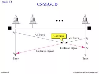
Figure 3-2 CSMA/CD
Figure 3-3 Ethernet layers
Figure 3-4 Ethernet frame
Transceivers are used to connect nodes to the various Ethernet media. Most computers and network interface cards contain a built-in 10BASE-T or 10BASE2 transceiver, allowing them to be connected directly to Ethernet without requiring an external transceiver. Many Ethernet devices provide an AUI (Attachment Unit Interface ) connector to allow the user to connect to any media type via an external transceiver. The AUI connector consists of a 15-pin D-shell type connector, female on the computer side, male on the transceiver side. Thickwire (10BASE5) cables also use transceivers to allow connections Transceivers
Figure 3-5:a Ethernet implementation
The Original Ethernet The first Ethernet (10Base5) used a bus topology and a thick coaxial cable. Transceivers connect the network adapters to the cable via a vampire tap that "bites" into the coax.
Figure 3-5:b Ethernet implementation
Thin Ethernet 10Base2 Ethernet was a later variation of the original 10Base5. It used a thinner coaxial cable attached to each node using BNC (bayonet Neil-Concelman) T-connectors
Figure 3-5:c Ethernet implementation
Twisted Pair Ethernet Most Ethernets use twisted pair wiring. All cables use RJ-45 connectors between the network adapters in the PC and a central hub or switch Ethernet Switch This 10/100 switch from Omnitron has 16 ports and automatically senses the transmission rate of the line and adjusts accordingly
Figure 3-5:d Ethernet implementation
Figure 3-6:a Fast Ethernet implementation
Figure 3-6:b Fast Ethernet implementation
Figure 3-6:c Fast Ethernet implementation
Figure 3-7:a Gigabit Ethernet implementation
Figure 3-7:b Gigabit Ethernet implementation