Download
1 / 106
1.07k likes | 1.21k Vues
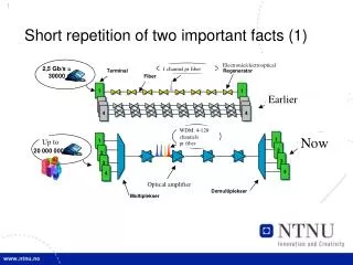
Electronic/electrooptical. 1 channel pr fiber. Earlier. WDM: 4-128 channels pr fiber. Now. Up to. Optical amplifier. Short repetition of two important facts (1). Wavelength converter. Optical crossconnect. Optical switches. Circuit switching

E N D
Electronic/electrooptical 1 channel pr fiber Earlier WDM: 4-128 channelspr fiber Now Up to Optical amplifier Short repetition of two important facts (1)
Wavelength converter Optical crossconnect Optical switches • Circuit switching • Switches signals between fibers and/or wavelengths. • Wavelength conversion • To avoid collision on wavelengths (in same fiber)
Repetition Outline: Optical components Transmission aspects Optical Transport Network –OTN- G. 709 Optical protection switching OPS/OBS
Optical fibre, characteristic • Large bandwidth (theoretical 50 THZ) • Low attenuation (0,2 dB/km at 1550nm). • Physical size beneficial, light and thin, simplifies installation • Splicing and mounting connectors more complex • Immune to electromagnetic interference • Environmentally friendly material (sand!).
Propagation through fibre • Lightpulses are reflected into the core when hitting the cladding => approximately zero loss Andreas Kimsås, Optiske Nett
Coupling light into the fibre • Single modus • Coupling into the tiny 10 micrometer core is demanding • Lining up the light-source is a significant part of the production cost • Multimode • Larger core diameter simplifies coupling
Modulation • OOK modulation (on-off-keying) • NRZ (No Return Zero) most often used • RZ (Return Zero), some use • Phase modulation currently not popular • More advanced modulation formats being launched for 40 Gb/s pr. Channel systems. • Directly modulated laser • For medium bitrates Gigabit • External modulation, e.g. Employing external modulator: MZ interferometer • For high bitrates 10 Gb/s and beyond
What is a long distance? • 100 m? • LAN • 10 Km? • Access network • 1000 Km? • Transport network
Long distance optical system • Attenuation must be compensated • Regeneration • Attenuation • Dispersion must be compensated • Dispersion compensation employing fibre • Electronic compensation
Regeneration • 1R regeneration = Amplification (Reamplification) • Amplifies the signal without conversion to electrical • Typically transparent for signal (shape, format and modulation) • Usually an optical amplifier • 2R Reamplification & Reshaping: • Reshapes the flanks of the pulse as well as the floor and roof of the pulse, removes noise. • Usually electronic • Optical solutions still subject to research • 3R Reamplification & Reshaping & Retiming: • Synchronisation to original bit-timing. (regeneration of clock) • Usually involves electro-optic conversion • Optical techniques in the research lab.
Erbium Doped Fiber Amplifier (EDFA) • Widely deployed in optical networks
Available wavelength range depends on amplifier technology PDFA 1300 nm EDFA C - band 1530-1562 EDFA L - band 1570-1600 ALTERNATIVE AMPLIFIER TECHNLOGIES: RAMAN AND SOA Commercially available Still subject to research
Dispersion • Pulse spreading when propagating through the fibre. • To much spreading results in intersymbol- interference • Limits the maximum transmissionrate through the fibre. • Three types of dispersion: • Modi-dispersion: Light traveling in different modi undergoes different delays through the fibre. Not present in SM! • Material-dispersion (chromatic): Refractive index is function of wavelength • Waveguide-dispersion: Propagation of different wavelengths depends on the characteristic of the waveguide, e.g. Index, geometry of core and cladding.
Zero dispersion • At 1300 nm in standard fibre • Material (chromatic) dispersion is close to zero at 1300 nm • Not minimum loss • ~ 1500 nm in dispersion shifted fibre • Manufactured for zero dispersion in 1500 nm region • Design core and cladding to give negative waveguide dispersion • At a specific wavelength, material and waveguide dispersion will result in zero total dispersion.
Chromatic dispersion Figure: S. Bigo, Alcatel: Talk at Norwegian electro-optics meeting 2004
Chromatic Dispersion in transmission fibre – key figures • Dispersion depends on fibretype • G652, “Standard fibre” -17 Ps/nm*km @ 1550 nm • Dispersion shifted fibre: 0 dispersion @ 1550 nm • Non – Zero (NZ) dispersion shifted fibre: -3 to -6 Ps/nm*km
Dispersion Compensating Fibre (DCF) • Negative dispersion compared to transmission fibre • Much higher dispersion/km => Shorter fibre than transmission fibre required for achieving zero dispersion
Long distance fibre-optical transmission Basic optical components(For WDM systems: Additional mux/dmux required Transmitter (Laser+ modulator) Receiver (fotodiode + amplifier) EDFA DCF Long Fibre Compensation of amplitude and dispersion
Optical couplers: splitter & combiner • One or more fibers in, several fibres out • Divides the optical signal on several fibres. • Signal power is divided on the output-fibres • Splitting ratio is varying • 50/50, 50 % on each of two fibres • 10/90, 10 % in one, 90 % in a second. • Attenuation from input to output depends on splitting ratio • 50/50 splitter results in 3 dB attenuation (halving the power) Combiner Splitter
Arrayed waveguide Grating • 1 X N or N X N coupler divides the light on N waveguides of different length • Waveguides is then coupled together, resulting in interference • On each of the N outputs, constructive interference is achieved for a specific wavelength and destructive interference for the other wavelengths
Multiplexing/Demultiplexing • Optical multiplexing: Couple several waveguides together into a fibre. • Optical demultiplexing: Separate wavelengths from an input fibre into several output fibres with a single wavelength in each. • Employed for mux/demux in optical network nodes
Optical add/drop • Filter out a wavelength or a set of wavelengths. • Does not employ non-linear effects • Add a wavelength or set of wavelengths. • May be reconfigurable (ROADM) • Select which wavelength to drop and add on a fibre • Not as configurable as an optical cross connect (full cross-connection between several fibres) l1,l2 l1,l2 l1 l1 Drop Add
Most important components • Optical fibre • Principle • Key parameters: Chromatic Dispersion, attenuation • Optical coupler • Principle • Application • EDFA Optical Amplifier • Principle • Application • AWG • Principle • Applications
2 dB/km G.652 G.652C 0,5 0,4 0,3 Loss (dB/km) 0,2 0,1 0 1200 1300 1400 1500 1600 Wavelength (nm) Coarse WDM • Cheaper technology with less scalability than DWDM • Typically maximum 16 channels 1271-1451 nm 1471-1611 nm
C1 – (8+1) C1– (8+1) EXT 1471 1491 1511 1531 1551 1571 1591 1611 1471 1491 1511 1531 1551 1571 1591 1611 EXT C1 – 8L C1 – 8L 1271 1291 1311 1331 1351 1371 1431 1451 1271 1291 1311 1331 1351 1371 1431 1451 16 channel CWDM using two multiplexers for two different bands
C1-8 C1–8 1471 1491 1511 1531 1551 1571 1591 1611 1471 1491 1511 1531 1551 1571 1591 1611 D1-52 D1-52 1535.82 1535.04 1534.25 1533.47 1532.68 1531.90 1531.12 1530.33 1535.82 1535.04 1534.25 1533.47 1532.68 1531.90 1531.12 1530.33 CWDM and DWDM hybrid
Optical networks (Zouganeli) • Increased traffic demands (e.g. from broadband home users/businesses and new services) => Fat pipes needed. • ”IP everywhere” and development in optical technology => Fokus on simplifications:
Reconfigurable (R-)OADM • Still use cross connect for some wavelength/wavebands, but introduce more flexible add-drop function: Not single wavelength!
Network element functionality: Bypass • Traffic bypassing intermediate IP routers => Less load on routers (can be smaller and cheaper) • In meshed networks:Used to directly connect node pairs with high traffic between them. • (UNINETT is in the process of doing this now).
Transparent (all-optical) switches (1) • Micro-electro-machining systems (MEMS) • Complicated, but has received a lot of attention.
Transparent (all-optical) switches (2) • Probably most promising alternative currently. • However: Tunable Wavelength Converters (TWCs) are very expensive.
Switching architectures with wavelength conversion (Borella) • Dedicated converters for each output • Many converters • Flexible, no blocking • Wavelength specific multiplexers minimizes attenuation.
Switches with shared wavelength conversion (Borella) • Shared between all input lines • Access from any input wavelength • Optimal wavelength converter resource utilization • WC may not be available if too few • Extra switch between WC and output MUX required.
Needed functionality for optical OXC based networks (1) • Opto-electronic or all-optical. • Scalability and flexibility • Handles much higher number of line ports and directions than R-OADM • Higher flexibility than R-OADM • Service provisioning: End-to-end lightpaths should be provisioned in an automated fashion (not necessarily all-optical or same wavelength end-to-end). • Protection and restoration: Must have mechanisms to protect against fiber cuts or equipment failure at nodes. I.e. redirect traffic from failed to backup paths. • Wavelength conversion: Lightpaths can change wavelength to increase flexibility in allocating network resources. Much easier to implement in opto-electronic OXC than in all-optical OXC;3R versus 2R (Mach-Zhender interferometer).
Needed functionality for optical OXC based networks (2) • Multiplexing and grooming: Normally done in the opto-electronical add-drop part. • Today mainly opto-electronic solutions. • Many candidate all-optical solutions: - Generic switch architectures (Clos, Shuffle,..) where elements are simple optical switch elements, connected with fibers. - ”Broadcast and select” switching matrixes realized with splitters and Semiconductor Optical Amplifiers (SOAs) (0 – 1 : block or let-through light).- Two- or three dimensional array of micro mirrors (MEMS)- Tunable wavelength converters and Array Waveguide Gratings (AWG)
1a) Fixed patch panel between WDM systems with transponders. 1b) Electrical switch fabric between WDM systems with transponders. 1c) Transparent switch between WDM systems with transponders, complemented by a OEO switch for drop traffic. 1d) Transparent switch on a transparent network. The signal stays optical until it exits the network. 4 different architectures
1c) Transparent switch between WDM systems with transponders, complemented by a OEO switch for control and management functions The optical switch fabric is bit-rate independent and accommodates any data rates available. Most lightpaths will bypass the OEO switch. The drop side ports are connected to an OEO switch that provides SONET/SDH line termination through its opaque ports.
Optical Transport Network (OTN) ITU-T standard G.709 Paper: Andreas Schubert: ”G.709 – The Optical Transport Network (OTN)” http://www.jdsu.com/product-literature/g709otn_wp_opt_tm_ae.pdf
Why OTN? • Standard for optical networks required • Optical interconnection between equipment from different vendors • Optical interconnection between different operators • Once called “digital wrapper” • Framing of different protocols for transport over the physical optical layer • E.g. IP/Ethernet or IP/ATM or SDH • Takes SDH/SONET further, enabling optical functionality • Six level Tandem connection monitoring (TCM) • From a single to multiple wavelengths • Forward Error Correction (FEC) • What is FEC?
OTN hierarchy Client Client OPU Client OH ODU OH OPUk OTU OH ODUk FEC OChannel OCh payload Non Associated overhead OCC OCCp OCCp OCCp OCCp OCCp OMS payload OTS payload
ODU OH TCM6 TCM4 TCM5 RES FTFL TCM/ACT TCM3 EXP PM TCM2 TCM1 GCC1 RES GCC2 APS/PCC • PM - Path Monitoring, contains three sub-fields • TCM1-TCM6 • OH for six independent TCM’s • Contains similar sub-fields as PM • TCM/ACT Activation/deactivation of TCM • GCC • Communication between network elements (management), two channels • APS/PCC • Automatic Protection Switching • Protection Communication Channel • RES Reserved for future use • EXP Experimental use • FTFL - Fault Type and fault location Channel • Fault status, type and location • Related to TCM span
FEC algorithms • Performance increase depends on algorithm and amount of overhead (redundancy information) • Standardized algorithms, G.709. Reed-Solomon based
Summary OTN • Management to the high bandwidth WDM network • SDH/SONET single wavelength, OTN – multiple wavelengths • Builds on management functionality from SDH/SONET • Monitoring functionality • GCC channels for management communication • Transparency to other protocols, e.g. IP • Wrap whatever you like • FEC compensates physical impairments, increases cost-efficiency
Summary OTN • Management to the high bandwidth WDM network • SDH/SONET single wavelength, OTN – multiple wavelengths • Builds on management functionality from SDH/SONET • Monitoring functionality • GCC channels for management communication • Transparency to other protocols, e.g. IP • Wrap whatever you like • FEC compensates physical impairments, increases cost-efficiency • OTN switching is being deployed • OTN transmission and switching market is increasing rapidly
Protection in mesh network (Also used in other networks) • 1+1 protection • Continuous signal on two alternative paths, choose the best. • Hitless protection switching possible (switching without loss) • 1:N protection • Several parties share a single common protection path. • Enables the path to be employed by low priority traffic when not in use. • Implies information loss because of switching. Data in the fibre is lost. Not hitless.
Protection schemes • Dedicating resources • Dedicated protection (e.g. separate dedicated wavelength) • 1+1 duplicating data, or 1:1, pre-empting low-pri. data • In context of rings these are called DPRings • Optical unidirectional path switched rings (OUPSRs), path • Optical unidirectional line-switched rings (OULSRs), line • Shared protection • Protection resources shared between several lightpaths • 1:N, requires signalling • In context of rings these are called SPRrings • Optical bidirectional path switched rings (OBPSRs), path • Optical bidirectional line-switched rings (OBLSRs), line
Classification of resilience schemes WDM • Restoration • Dynamic lookup for backup paths, spare capacity in the network. Typical IP-layer. • Protection • Reserving dedicated backup paths in advance. Typical WDM layer.
Protection times • SONET/SDH • 60/50 milliseconds for establishing a connection. • May avoid interruptions in a phone call. • Optical layer • 2 micro – 60 milli seconds. • SONET detects errors within 2.3 – 100 micro seconds. Protection at higher layers may be initiated. • IP-layer • Slow detection, calculation and signalling, typically seconds. • MPLS • Relatively fast detection with HELLO messages, the higher frequency of the messages, the higher the overhead. • Fast switching if pre-planned path, LSP.
Carrier-Grade Ethernet Technology Based on the article: “Ethernet as a Carrier Grade Technology: Developments and Innovations” by R. Sanchez, L. Raptis, K. Vaxenavakis
Native Ethernet characteristics Ethernet Frame: 1) 7octets Preamble for synchronization 2) SFD (10101011) start of MAC frames 3) 48 bit DestinationAdress, 48 bit SourceAddress • Simplicity (plug n’play) and cost effective • The switching logic (self-configuration) • Listening, Learning and Forwarding • Redundancy through xSTP • VLAN known as a broadcast domain • Connection-less (single hop) • CSMA/CD (do we still need it in switched Ethernet?)