Download
1 / 30
370 likes | 762 Vues
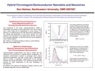
Properties and Fabricating Technique of Tunneling Magnetoresistance. Reporter : Kuo-Ming Wu Day : 2006/04/08. Outline. Development of Spintronics Tunneling Magnetoresistance Spin Torque Transfer Conclusion. Development of Spintronics. Spin elec tronic : Spintronics.

E N D
Properties and Fabricating Technique of Tunneling Magnetoresistance Reporter : Kuo-Ming Wu Day:2006/04/08
Outline Development of Spintronics Tunneling Magnetoresistance Spin Torque Transfer Conclusion
Development of Spintronics Spin electronic: Spintronics The spin induced ferromagnetic phenomena has a large application valuation, and hence builds on the Spintronics that the device working principle depends on the electron spin direction.
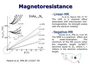
Development of Spintronics • The lower density of state of the spin-up than that of spin-down one at Fermi-level energy. • The majority and minority spin electrons play important roles of the magneto-electric behaviors, such as magnetoresistance(MR).
Development of Spintronics The MR ratio is the variation of the sample resistance under different magnetic field.
EF n↑(EF) n↓(EF) Majority Minority Tunneling Magnetoresistance The energy band structure the 3d ferromagnetic materials near the Fermi level, such as Fe, Co, Ni
↑ ↑ Tunneling Magnetoresistance Parallel-state
↑ ↓ Tunneling Magnetoresistance AntiParallel-state
Tunneling Magnetoresistance M. Julliere Phys. Lett. A 54 225 (1975)
Tunneling Magnetoresistance J. G. Simmons, J. Appl. Phys. 34,2581(1963)
→ → ← ← → → ← ← ← → ← → → → ← ← Tunneling Magnetoresistance Ta 20/CoFe 25/AlOx 1.2/NiFe 30/Ta 40
Tunneling Magnetoresistance Ta 20/CoFe 25/AlOx 1.2 or 1.5/NiFe 30/Ta 40
→ → → ← ← ← ← → ← → ← → ← ← → → Tunneling Magnetoresistance Ta 20/MnIr 12/CoFe 3/AlOx 1.2/CoFe 3 /NiFe 45/Ta 20
← → Spin Torque Transfer Jc:5x10⁶ A/cm2
Spin Torque Transfer • In 1996, Slonczewski and Berger predicted that the magnetization of a magnetic layer can be reversed by injection of a spin polarized current and spin transfer to the layer. • Magnetization reversal without application of an external magnetic field would be of considerable interest to switch magnetic microdevices.
Spin Torque Transfer Slonczewski brought out that polarized spin current contribute torque is equal to: Where γis the gyromagnetic ratio Heff is effect magnetic field c is the direction of symmetry axis of anisotropy αis the damping coefficient
Spin Torque Transfer Write to parallel
Spin Torque Transfer Write to antiparallel
→ ← Spin Torque Transfer SiO2/Ta 20nm/PtMn 15nm/CoFeB 3nm/Ru 0.8nm/CoFeB 3nm / AlOx 0.7 before oxide/CoFeB 2nm/Ta 40 nm
holder holder holder Spin Torque Transfer 45° etching 75° etching 0° etching Beam Beam Beam Redeposition
Source Chamber ICP Power Coil (13.56 MHz) Wafer ProcessChamber Bias Power (13.56 MHz) Coller Spin Torque Transfer Inductively Coupled Plasma Reactive Ion Etching
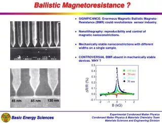
Spin Torque Transfer 500 x 250 nm 130 x 130 nm
Conclusion • Spin torque transfer effect is more competent than field induced switching for TMR or GMR nano-devices. • ICP-RIE etching procures higher taper angle and less damage than Ion Beam Etching for TMR fabrication process.