Download
1 / 24
240 likes | 267 Vues
Learn about separating architecture from implementation, MIPS operations, processor organization, VHDL basics, and levels of digital system description using VHDL. Practice designing hardware components through VHDL examples.

E N D
14:332:331Computer Architecture and Assembly LanguageFall 2003Week 5 [Adapted from Dave Patterson’s UCB CS152 slides and Mary Jane Irwin’s PSU CSE331 slides]
Head’s Up • This week’s material • Introduction to VHDL • Reading assignment – Y, Chapters 1 through 3 • Next week’s material • VHDL modeling • Reading assignment – Y, Chapter 4 and 5 • MIPS arithmetic operations • Reading assignment – PH 4.1 through 4.3
To make the architect’s crucial task even conceivable, it is necessary to separate the architecture, the definition of the product as perceivable by the user, from its implementation. Architecture versus implementation defines a clean boundary between parts of the design task, and there is plenty of work on each side of it. The Mythical Man-Month, Brooks, pg. 256
Fetch PC = PC+4 Exec Decode Review: MIPS Organization, so far Processor Memory Register File 1…1100 src1 addr src1 data 5 32 src2 addr 32 registers ($zero - $ra) 5 dst addr read/write addr 5 src2 data write data 32 230 words 32 32 32 bits br offset read data 32 Add PC 32 32 32 32 Add 32 4 write data 0…1100 32 0…1000 32 4 5 6 7 0…0100 32 ALU 0 1 2 3 0…0000 32 word address (binary) 32 bits 32 byte address (big Endian)
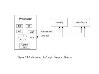
Processor Organization • Processor control needs to have the • Ability to input instructions from memory • Logic to control instruction sequencing and to issue signals that control the way information flows between the datapath components and the operations performed by them • Processor datapath needs to have the • Ability to load data from and store data to memory • Interconnected components - functional units (e.g., ALU) and storage units (e.g., Register File) - for executing the ISA • Need a way to describe the organization • High level (block diagram) description • Schematic (gate level) description • Textural (simulation/synthesis level) description
Less Abstract More Accurate Slower Simulation Schematic capture + logic simulation package like LogicWorks Special languages + simulation systems for describing the inherent parallel activity in hardware (VHDL and verilog) Levels of Description of a Digital System Architectural Functional/Behavioral Register Transfer Logic Circuit models programmer's view at a high level; written in your favorite programming language more detailed model, like the block diagram view model is in terms of datapath FUs, registers, busses; register xfer operations are clock phase accurate model is in terms of logic gates; delay information can be specified for gates; digital waveforms model is in terms of circuits (electrical behavior); accurate analog waveforms
Why Simulate First? • Physical breadboarding (as in CSE 275) • discrete components/lower scale integration precedes actual construction of the prototype • verification of the initial design • No longer possible as designs reach higher levels of integration! • Simulation before construction - aka functional verification • high level constructs means faster to design and test • can play “what if” more easily • limited performance (can’t usually simulate all possible input transitions) and accuracy (can’t usually model wiring delays accurately), however
Entity== External Characteristics Architecture (Body ) == Internal Behavior or Structure (VHSIC Hardware Description Language) VHDL • Goals: • Support design, documentation, simulation & verification, and synthesis of hardware • Allow integrated design at multiple levels - behavioral and structural (gate level) • Concepts: • Design entity-architecture descriptions • Time-based execution (discrete event simulation) model Design Entity-Architecture == Hardware Component
Entity Interface • Externally visible characteristics • Ports: channels of communication • (inputs, outputs, clocks, control) • Generic parameters: define class of components • (timing characteristics, size, fan-out) entity name_of_component is port(a,b: in std_logic; y: out std_logic); end name_of_component;
Architecture Body • Internal behavior or structure of circuit • Declaration of module’s internal signals • Description of behavior of circuit • concurrent behavioral description - collection of Concurrent Signal Assignment (CSA) statements executed concurrently • process behavioral description - CSAs and variable assignment statements within a process description • structural description - system described in terms of the interconnections of its components architecture behavioral of name_of_component is signal s1,s2: std_logic; begin - description of behavior of ports and signals; end behavioral;
VHDL Example: nor-nor gate a t0 b y c entity nor_nor_logic is port (a,b,c: in std_logic; y: out std_logic); end nor_nor_logic; architecture concurrent_behavior of nor_nor_logic is signal t0: std_logic; begin t0 <= a nor b; y <= t0 nor c; end concurrent_behavior;
Things to Notice • <= indicates a Concurrent Signal Assignment (CSA) • like “real” logic, nor_nor “process” is in an infinite loop • t0 and y are signals, not variables • they change when ever the inputs (a, b, or c) change • std_logic conforms to the IEEE 1164 standard library IEEE; use IEEE.std_logic_1164.all; entity nor_nor_logic is ...
Modeling Delays • Can model temporal, as well as functional behavior, with delays in CSAs • t0 changes 1 ns after a or b changes entity nor_nor_logic is port (a,b,c: in std_logic; y: out std_logic); end nor_nor_logic; architecture concurrent_behavior of nor_nor_logic is signal t0: std_logic; begin t0 <= (a nor b) after 1 ns; y <= (t0 nor c) after 1 ns; end concurrent_behavior;
Review: VHDL • Goals: • Support design, documentation, simulation & verification, and synthesis of hardware • Allow integrated design at multiple levels - behavioral and structural (gate level) • Concepts: • Design entity-architecture descriptions • Time-based execution (discrete event simulation) model Entity== External Characteristics Design Entity-Architecture == Hardware Component Architecture (Body ) == Internal Behavior or Structure
Review: An Entity-Architecture Example a t0 b y c entity nor_nor_logic is port(a,b,c: in std_logic; y: out std_logic); end nor_nor_logic; architecture concurrent_behavior of nor_nor_logic is signal t0: std_logic; begin t0 <= (a nor b) after 1 ns; y <= (t0 nor c) after 1 ns; end concurrent_behavior;
Entity-Architecture Features • Entity defines externally visible characteristics • Ports: channels of communication • signal names for inputs, outputs, clocks, control • Generic parameters: define class of components • timing characteristics, size (fan-in), fan-out • Architecture defines the internal behavior or structure of circuit • Declaration of internal signals • Description of behavior • concurrent behavioral description: collection of Concurrent Signal Assignment (CSA) statements (indicated by <=) executed concurrently; can also model temporal behavior with the delay annotation • process behavioral description: CSAs and variable assignment statements within a process description • structural description: system described in terms of the interconnections of its components
New Object: Signals • Digital systems are about signals, not variables signal<=value expressions after time expression • signals are analogous to wires and change when ever their inputs change - time-value pairs resulting in a waveform • std_logic conforms to the 9-value IEEE 1164 standard for signals When a signal has multiple drivers (e.g., a bus), the value of the resulting signal is determined by a resolution function for std_logic and std_logic_vector the resolution function (lookup table) is provided by std_logic_1164 package
Model of Execution • CSA’s are executed concurrently - textural order of the statements is irrelevant to the correct operation • Two stage model of circuit execution • first stage • all CSA’s with events occurring at the current time on signals on their right hand side (RHS) are evaluated • all future events that are generated from this evaluation are scheduled on the events list • second stage • time is advanced to the time of the next event • VHDL programmer specifies • events - with CSA’s • delays - with CSA’s with delay annotation • concurrency - by having a distinct CSA for each signal
Constant Objects • Constant parameters provide default values • may be overridden on each instance • attach value to symbol as attribute entity nor_nor_logic is port(a,b,c: in std_logic; y: out std_logic); end nor_nor_logic; architecture concurrent_behavior of nor_nor_logic is signal t0: std_logic; constant gate_delay: Time := 1 ns; begin t0 <= (a nor b) after gate_delay; y <= (t0 nor c) after gate_delay; end concurrent_behavior;
Bit-Vector Data Types • Std_logic_vector (31 downto 0) is equivalent to a 32-bit bus • Can convert it to a 32 bit integer entity nand32 is port(a,b: in std_logic_vector (31 downto 0); y: out std_logic_vector (31 downto 0)); end nand32; architecture concurrent_behavior of nand32 is begin y <= a nand b; end concurrent_behavior; • Analyzer (compiler) expands the architecture into 32 2-input nand gates with the inputs connected appropriately
Conditional Signal Assignment Statement • Conditional CSA • order is important - the first conditional expression that evaluates to true determines the output signal S0 S1 In0 entity mux4 is port(In0,In1,In2,In3: in std_logic_vector (7 downto 0); S0,S1: in std_logic; Z: out std_logic_vector (7 downto 0)); end mux4; architecture behavior of mux4 is begin Z <= In0 after 5 ns when S0 = ‘0’ and S1 = ‘0’ else In1 after 5 ns when S0 = ‘0’ and S1 = ‘1’ else In2 after 5 ns when S0 = ‘1’ and S1 = ‘0’ else In3 after 5 ns when S0 = ‘1’ and S1 = ‘1’ else “00000000” after 5 ns end behavior; 00 In1 01 Z In2 10 In3 11
Selected Signal Assignment Statement • Selected CSA • all choices are evaluated, but only one must be true entity reg_file is port(addr1,addr2: in std_logic_vector (1 downto 0); dout1, dout2: out std_logic_vector (31 downto 0)); end reg_file; architecture behavior of reg_file is signal reg0: std_logic_vector (31 downto 0) := to_stdlogicvector (x”00000000”); signal reg1,reg2: std_logic_vector (31 downto 0) := to_stdlogicvector (x”ffffffff”); begin with addr1 select dout1 <= reg0 after 5 ns when “00”, <= reg1 after 5 ns when “01”, <= reg2 after 5 ns whenothers; with addr2 select dout2 <= reg0 after 5 ns when “00”, <= reg1 after 5 ns when “01”, <= reg2 after 5 ns whenothers; end behavior;
Summary • Introduction to VHDL • A language to describe hardware • entity = symbol, architecture ~ schematic, signals = wires • Inherently concurrent (parallel) • Has time as concept • Behavioral descriptions of a component • can be specified using CSAs • can be specified using one or more processes and sequential statements • Structural descriptions of a system are specified in terms of its interconnections • behavioral models of each component must be provided

![LAB [ 2 ]](https://cdn1.slideserve.com/2335586/lab-2-dt.jpg)