Walchem W600 Overview: Menu & Settings
140 likes | 164 Vues
The Walchem W600 controller offers flexibility and performance, featuring a large custom LCD touch screen display and user-defined inputs and outputs. Learn about the menu structure and basic functions for easy setup and maintenance.

Walchem W600 Overview: Menu & Settings
E N D
Presentation Transcript
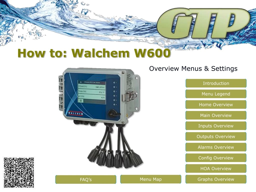
How to: Walchem W600 Overview Menus & Settings Introduction Menu Legend Home Overview Main Overview Inputs Overview Outputs Overview Alarms Overview Config Overview HOA Overview Menu Map Graphs Overview FAQ’s
Introduction Large Custom LCD Display Walchem W600 controller is designed on a universal platform for flexibility and performance. With a large custom LCD touch screen display and a symbol based menu icons setup, care and maintenance is a breeze. Features Include: Large custom LCD touch screen display User defined inputs & outputs Single or dual sensor input Contacting & Electrodeless Cond Sensors pH, ORP & Disinfection Sensors Six user defined relay outputs 115VAC or Dry Relays Pulse Proportional Relays Six user defined digital inputs Flowswitch, Water Meter or Flow Sensor Datalogs and Graphs Optional 4-20mA inputs and outputs Optional LAN Connection & Modbus TCP LCD Touch Screen Relay Indicators 6 User Defined Relay Outputs Sensor & Digital Inputs
Menu Legend With the universal platform of the W600 controller sometimes allow for more flexibility than what was bargained for and sometime the simple task get lost. Let go over the basics. Icon Based Menu Systems. In the legend to the right, you can see the basics for their menu system. Keep these in mind as we go through this training session. When in doubt, start again or call and we can hep get you back on track. If something just does not feel right, or is not working the way you want, we can either help guide you through it or reset the controller back to factory settings. Software Upgrades are always free. This training is based on current software, making sure you are update will give us the best view of what’s going on and where to go.
Home Overview Home Screen: The home screen is user definable (so yours may look different) and will show you up to 8 settings (4 revolving at a time) and top of screen is devoted to alarm(s) conditions. Lower left hand corner will pull up the Main Menu Screen which we will go over next, but pressing anyone of the displayed values, will take you directly to that part of the software. Example: On our display to the right, if you pressed the screen where it say CCond (S11) you would go directly to the Conductivity Sensor Input screen so you could maintain it or calibrate it. The same would go for the Temp (S12) and so on… Let’s go to the Main Menu by pressing the lower left menu symbol
Main Overview Main Menu: The main menu screen will help navigate to what you need to do. There are six subcategories, inputs, outputs, alarms, configuration, hand/off/auto an graphs. Know where you stuff is, will help navigate directly to it. Lower left corner now displays a home button to go back to the home screen. Menu choices are: Inputs Menu Output Menu Alarms Menu Config Menu HOA Menu Graphs Menu Refer to the manual for details or contact us for help. See FAQ section at the end of this presentation for guidance to common sections of the controller.
Inputs Overview Inputs Menu: The inputs are any item the controller has going to it, such as: Sensors Inputs (S_) : Conductivity, pH, ORP and Disinfection Digital Inputs (D_) : Flow switches, Level Switches, Flow meters and Flow Sensors Analog Inputs (AI_) : Little Dipper Sensors and Level and Flow Transmitters Virtual Sensors (V_) : NEW Virtual sensors let you take any two similar inputs, and compare them with a calculation, then control on that value. Like cycles of concentration, or water usage based on incoming and out going water meters. Refer to the manual for details or contact us for help. See FAQ section at the end of this presentation for guidance to common sections of the controller.
Output Overview Output Menu: The are any control function headed out of the machine, such as: Control Relays (R_) : Either powered, pulsing or dry control relays for valves, pumps, BMS systems or alarms Analog Output (AO_) : 4-20 mA output for chart recorders, pumps, BMS systems or control valves. Refer to the manual for details or contact us for help. See FAQ section at the end of this presentation for guidance to common sections of the controller.
Alarms Overview Alarms Menu: Will detail out what current alarms are on the controller. Use the sensor, relay, etc. indicators to figure where to go to correct condition Example: Flowswitch (D1) would be in the digital inputs menu, digital input #1. CCond (S11) would be in the sensor menu, sensor input #11. On/Off (R1) would be in the output menu, relay #1. If you need more help, please call. Refer to the manual for details or contact us for help. See FAQ section at the end of this presentation for guidance to common sections of the controller.
Config Overview Config Menu: This menu is to setup units of measure, times and date, controller name, export/import files, datalogs and board status. Menu items are: Global Settings Security Settings Display Settings File Utilities Controller Details Refer to the manual for details or contact us for help. See FAQ section at the end of this presentation for guidance to common sections of the controller.
HOA Overview HOA Menu: Lets you turn on and off relays for maintenance, testing and priming and return them to auto when finished from one screen. Refer to the manual for details or contact us for help. See FAQ section at the end of this presentation for guidance to common sections of the controller.
Graphs Overview Graphs Menu: The graph menu will give a one sensor, one relay view of the controller for troubleshooting. This view is user defined and very helpful when trying to see what happed. Refer to the manual for details or contact us for help. See FAQ section at the end of this presentation for guidance to common sections of the controller.
This overview should answer a few questions. The upper right is the MAIN menu. Dash lines lead from buttons and symbol legend defines icons. A larger PDF version is available on our website.
FAQ’s Sensor Calibration: This will be in the inputs menu, pan to and press sensor to calibrate, press the crosshair symbol. Change/Configure Blowdown: This will be in the output menu. Pan to and press the relay you want to use for blowdown, press maintenance button, make sure relay in the in proper mode by panning to bottom of listing (should be on/off set point), change set point and Deadband as needed. Change/Configure Feed: This will be in the output menu. Pan to and press the relay you want to use for feed, press maintenance, and pan to the bottom of list to make sure relay is in the proper mode. Popular choices are feed & bleed, feed then bleed or flow timer. Relay is programmed but does not come on: Make sure the relay is in the auto mode, if so, make sure it is not interlocked with something it should not be. Controller still bleeds when no flow: Make sure interlock is set with Flowswitch. I cannot calibrate the controller: Make sure proper sensor is chosen and when used, the temperature portion of that sensor is properly set up. For safety reasons the controller will only allow the controller to modify what it thinks it is (raw value) 1.5 times. After that the sensor should be replaced. Which Calibration should I use: There are a few, and depending on the application you should use the most effective. Basic applications that are not regulated or inspected can use the one point process or one point buffer mostly. Two point buffer is best for more stringent application and should always be use on pH/ORP installation. This will provide a slope. Disinfection will have two types of calibration, buffer and a zero calc. Best to do both. When changing/replacing sensors please, start fresh and reset calibration values. Contact us for further help.
Contact Us Mailing Address: General Treatment Products P.O. Box 8697 Brea, CA 92822-5697 Shipping Address: General Treatment Products 113 Viking Ave. Brea, CA 92821 Phone: 714) 257-9165 FAX: 714) 257-9215 Internet:http://www.gtpcompany.com E-Mail:customerservice@gtpcompany.com


