Download
1 / 44
470 likes | 746 Vues
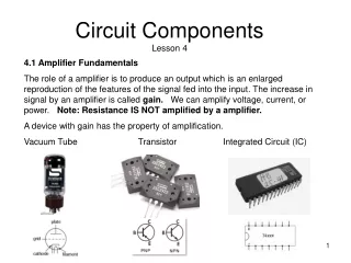
Characterization of Circuit Components Using S-Parameters. Chapter 1. Topic. S-Parameters S1P S2P Y-Parameters Components Wires Inductors Resistors Capacitors S-parameter Extraction. One-Port S-Parameter. Incident wave (V 1 + ) is V in /2 (as if Z in =R S )

E N D
Characterization of Circuit Components Using S-Parameters Chapter 1
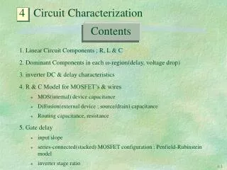
Topic • S-Parameters • S1P • S2P • Y-Parameters • Components • Wires • Inductors • Resistors • Capacitors • S-parameter Extraction
One-Port S-Parameter Incident wave (V1+) is Vin/2 (as if Zin=RS) Voltage at the input of the receiver is Zin/(Zin+RS)Vin Vin=V1-+V1+ V1-=Vin -V1+ V1-= Zin/(Zin+RS)Vin- Vin/2 =(Zin-RS)/[2(Zin+RS)]Vin V1-/ V1+ =(Zin-RS)/(Zin+RS)
One-Port S-Parameter Series RLC with resonant frequency at Resistance at resonant frequency: RL
Design a Series RLC Resonant Circuit RL=50 Ω L1=2.4 mH RS=50 Ω fres=1 MHz What is C1?
Design a Series RLC Resonant Circuit RL=50 Ω L1=2.4 mH RS=50 Ω fres=1 MHz What is C1? C1=1/(Lω2res)
One-Port S-parameter Power reflected to the source Power delivered to the load
Two-Port S-parameter Incident wave into the output port or wave reflected from RL Incident Wave generated by Vin Reflected wave Actual voltage measured at the input of the two-port network: V1++V1- Actual voltage measured at the output of the two-port network: V2++V2-
Y-Parameters Yo=1/Zo
Wires • In the AWG system, the diameter of a wire will roughly double every six wire gauges. E.g.
Skin Depth The skin depth is thus defined as the depth below the surface of the conductor at which the current density has fallen to about 37% of its surface current density.
Inductance of a Straight Wire • breadboard wire: 22 AWG or 25.3 mils in diameter. • Each mil =25.4 um or 0.0643 cm. • 5 cm of a No. 22 copper wire produce about 50 nH of inductance.
Resistors • Carbon-composition resistor • Wirewound resistor • Carbon-film resistor
Carbon-Composition Resistors Carbon composition resistors consist of a solid cylindrical resistive element with embedded wire leads. The resistive element is made from a mixture of finely ground (powdered) carbon and an insulating material (usually ceramic). The resistance is determined by the ratio of the fill material (the powdered ceramic) to the carbon. Higher concentrations of carbon, a good conductor, result in lower resistance. The parasitic capacitance arises out small capacitance between carbon fill. More expensive than carbon film resistor.
Wirewound Resistors • Wirewoundresistors are commonly made by winding a metal wire around a ceramic core. • The inductance is much larger than a carbon composition resistor • Poor temperature drift coefficient • Too much L and C to be useable at high frequencies
Carbon Film Resistor • Less expensive than carbon-composition resistors • Can drift with temperature and vibration • A carbon film is deposited on an insulating substrate, and a helix is cut in it to create a long, narrow resistive path. (Partially exposed)
Example 8.7 nH 8.7 nH 10K 0.3 pF Impedance associated inductor is negligible At 200 MHz A 10 Kohm resistor looks like a 2564.3 resistor at 200 MHz.
Impedance at 200 MHz 10 Kohm At DC
Extract Resistance from Y11 R=1/(0.0001) =10 KΩ
Extract Capacitance (1) Slope is constant!
Extract Capacitance (2) C=Y11imag_deriv/2/π=1.88 pF/2/3.1416=0.2992 pF
Generic Equivalent Circuit for a Capacitor L: inductance of the leads Rp: account for leakage current
Quality Factor of a Simplified Capacitance Model Quality factor= Im[Z]/Re[Z] =1/(ωRC)
Generic Equivalent Circuit for an Inductor Series resistance +skin resistance
Parasitic Resistance of an Inductor R=1/0.033=30.3 Ω
Inductance Extraction L=R/(2πfL) =29.73 nH
Parasitic Capacitance of an Inductor Capacitance: 117.14 fF
Quality Factor of a Simplified Inductor Circuit Model Q=Quality factor= Im[Z]/Re[Z] =(ωL) /(R) Larger Q, better inductor