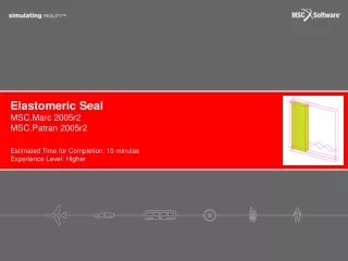
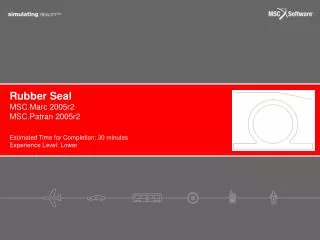
Rubber Seal
Rubber Seal. MSC.Marc 2005r2 MSC.Patran 2005r2. Estimated Time for Completion: 30 minutes Experience Level: Lower. Topics Covered. Using large displacement large strain analysis Defining rigid contact boundary condition for translational and rotational motion

Rubber Seal
E N D
Presentation Transcript
Rubber Seal MSC.Marc 2005r2 MSC.Patran 2005r2 Estimated Time for Completion: 30 minutes Experience Level: Lower
Topics Covered • Using large displacement large strain analysis • Defining rigid contact boundary condition for translational and rotational motion • Creating multiple step analysis • Using Mooney-Rivlin material model
Problem Description • In the design of a door seal, it is important to determine the maximum stresses experienced by the seal when the door is closed. This information can be used to estimate a life of the component under stresses. • The door is assumed rigid compared to the seal. It is first translated without rotation toward the seal 0.3” and then rotated 30 degrees counterclockwise. The seal is made of rubber whose behavior can be modeled using a Mooney-Rivlin model. • We will use Patran to complete the problem description from a given 2D meshed model and analyze it by using Marc.
Summary of Model First node is to control translation <0,-0.3,0> Rigid contact with 2 control nodes Second node is to control rotation <0.5236,0,0> Door Deformable contact Material using Mooney-Rivlin model C10 = 80 C01 = 20 Seal Constrain vertical and horizontal directions on all bottom nodes <0,0,>
Goal In this Example, we analyze a door seal. The purpose of the analysis is to examine the stresses and deflections created during the closing of a door. The door is considered very stiff relative to the rubber seal and can be modeled using a rigid body.
Expected Results Maximum tensile stress is 158 psi. Maximum compressive stress is 176 psi.
Create Database a b c d e • Click File menu / Select New • In File Name enter seal.db • Click OK • Select Analysis Code to be MSC. Marc • Click OK
Import Model a b c d • Click File menu / Select Import • Select Source to be MSC. Patran DB • Locate and select file seal_model.db • Click Apply
Create Control Nodes a b c d e f g h i • Click Elements icon • Click Node Size icon to see all nodes • Select Action to be Create • Select Object to be Node • Select Method to be Edit • In Node Location List, enter [-0.6,0.8,0] • Click Apply • In Node Location List, enter [0.06,0.8,0] • Click Apply Notes: These two nodes will be used to control the translation and rotation of the door
Create Fixed Displacements a b c d e f g h i j k l m n • Click Loads/BCs icon • Select Action to be Create • Select Object to be Displacement • Select Type to be Nodal • In New Set Name, enter fixed • Click Input Data • In Translations, enter <0,0, > • Click OK • Click Select Application Region • Select Geometry Filter to be FEM • Select all nodes at bottom of seal • Click Add • Click OK • Click Apply
Create Deformable Contacts a b c d e f g h i j • Select Object to be Contact • Select Option to be Deformable Body • In New Set Name, enter seal_contact • Select Target Element Type to be 2D • Click Select Application Region • Select Geometry Filter to be Geometry • Select all surfaces of the seal on screen or enter Surface 1:7 • Click Add • Click OK • Click Apply
Create Rigid Contacts a b c d e f g h i j k l m n • Select Option to be Rigid Body • In New Set Name, enter door_contact • Select Target Element Type to be 1D • Click Input Data • Select Motion Control to be Force/Moment • In First Control Node, select the node at the center of the door or enter Node 2000 • In Second Control Node, select the node on the left of thedoor or enter Node 1999 • Click OK • Click Select Application Region • Select Geometry Filter to be Geometry • Select all curves of the door on screen or enter Curve 1 2 • Click Add • Click OK • Click Apply
Create Displacements a b c d e f g h i j • Select Object to be Displacement • In New Set Name, enter translate1 • Click Input Data • In Translations, enter <0,-0.3,0> • Click OK • Click Select Application Region • Select Geometry Filter to be FEM • In Select Nodes, select the node at the center of the door or enter Node 2000 • Click Add • Click OK Repeat (b) – (j) for the following: The second control node defined in rigid contact is used to control rotation in radian (positive counterclockwise). This rotation is specified by T1 component in translation textbox.
Create Load Cases a b c d e f g • Click Load Cases icon • Select Action to be Create • In Load Case Name, enter translate • Click Input Data • Select fixed, rotate1, translate1, seal_contact, and door_contact • Click OK • Click Apply Repeat (c) – (g) for the following:
Define Material a b c d e f g h i • Click Materials icon • In Material Name,enter rubber • Click Input Properties • Select Constitutive Model to be Hyperelastic • Select Model to be Mooney-Rivlin • In Strain Energy Function, C10, enter 80 • In Strain Energy Function, C01, enter 20 • Click OK • Click Apply
Define Element Properties a b c d e f g h i j k l • Click Properties icon • Select Object to be 2D • Select Type to be 2D Solid • In Property Set Name, enter seal_prop • Select Options to be Plain Strain and Standard Formulation • Click Input Properties • Click Mat Prop Name icon and select rubber • In [Thickness], enter 1 • Click OK • In Select Members, select all surfaces of the seal on screen or enter Surface 1:7 • Click Add • Click Apply
Create Load Steps a b c d e f g h i j • Click Analysis icon • Click Load Step Creation • In Load Step Name, enter translate step • Click Select Load Case • Select translate • Click OK • Click Apply Repeat (c) – (g) for the following:
Run Analysis and Read Results File a b c d e f g h i Select load step • Click Load Step Selection • In Step Select, select translate step, rotate step, and unselect Default Static Step • Click OK • Click Apply ** Wait until analysis is completed ** Read results file • Select Action to be Read Results • Click Select Results File • Locate file seal.t16 • Click OK • Click Apply
Plot Results a b c d e f • Click Results icon • In Select Result Cases, select the last increment • In Select Fringe Result, select Stress, Global System • Select Quantity to be Max Principal • In Select Deformation Result, select Displacement, Translation • Click Apply Repeat (d) – (f) for Min Principal Maximum tensile stress is 158 psi. Maximum compressive stress is 176 psi.