Lecture 26
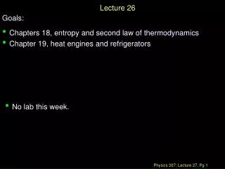
Lecture 26. ANNOUNCEMENTS Homework 12 due Thursday, 12/6. OUTLINE Self-biased current sources BJT MOSFET Guest lecturer Prof. Niknejad. Review: Current Mirrors. The current mirrors we discussed require a “golden” current source, I REF , to copy. Review: Current Mirrors (cont’d).


Lecture 26
E N D
Presentation Transcript
Lecture 26 ANNOUNCEMENTS • Homework 12 due Thursday, 12/6 OUTLINE • Self-biased current sources • BJT • MOSFET • Guest lecturer Prof. Niknejad
Review: Current Mirrors • The current mirrors we discussed require a “golden” current source, IREF, to copy.
Review: Current Mirrors (cont’d) • In lab 6 and lab 10, you used a resistor as your current source. • Q: What are some problems associated with this method?
Review: Current Mirrors (cont’d) • A: Variations in VCC and temperature cause significant variations in IREF. Consider the following analysis (ignoring base currents and the Early effect): • Thus, a 10 % change in VCC results in a 11.6 % change in IREF.
Base-emitter Reference • Rather than having a source dependent on VCC, why not use some other reference? • For example, a VBE referenced current source. • Ignoring base currents, we have: • Q: Why is this less supply dependent?
Base-emitter Reference (cont’d) • A: Although IIN varies almost directly with VCC, VBE1 won’t vary nearly as much, since the device is exponential. Since IOUT depends only on VBE1, the output won’t vary much with VCC. • Example: • Assuming VBE1 = 0.7 V, a change in input current by 10X causes an output current change of 8.7 %.
Self Biasing • We can do better than the VBE referenced source using feedback. What if our source had a current mirror attached that fed back the output current to act as the input current?
Self Biasing (cont’d) • Here, we’ve attached a pnp current mirror to force IOUT and IIN to match. • There are two stable operating points: • IIN = IOUT = 0 A • Desired operating point
Start-up Circuit • Need a way to “start-up” the circuit, like a car starter starts up your car. • Requirements: • Must keep the circuit out of the undesired operating point • Must not interfere with the circuit once it reaches the desired operating point
Start-up Circuit (cont’d) • Let’s ensure this works: • Assume IIN = IOUT = 0. This means approximately that VBE1 = VBE2 = 0. However, note that the left side of D1 is four diode drops from ground, meaning D1 is on. This drops some voltage across Rx, forcing current to flow into T1 and T2, starting up the circuit. • After the circuit is at the desired operating point, turn D1 off by ensuring RxIIN (the drop across Rx) is sufficiently large.
MOSFET Current Source • We can build an analogous circuit from MOSFETs as well. Let’s start with a VTH referenced current source. • If we make Vov1 small (by sizing up T1 or using small currents), IOUT is controlled primarily by VTH and R2.
MOSFET Current Source (cont’d) • Let’s add the current mirror feedback.
MOSFET Current Source (cont’d) • Finally, the start-up circuitry. It’s more typical to use more MOSFETs in MOS technologies rather than diodes.
MOSFET Current Source (cont’d) • Assume IIN = IOUT = 0. This means VGS1 = 0, meaning T8 is in triode. This turns on T9 and forces current to flow into T4 and T5. • Once in steady state, we can size T7 to ensure that T9 turns off. T7 and T8 don’t directly affect the circuit themselves, so the start-up circuit has done its job.
References • Material and figures largely from Analysis and Design of Analog Integrated Circuits, Fourth Edition by Gray, Hurst, Lewis, and Meyer.
Guest Lecturer: Prof. Ali Niknejad • Faculty director of the Berkeley Wireless Research Center (BWRC). Primary research interests include analog integrated circuits, mm-wave CMOS, RF and microwave circuits, device modeling (BSIM), electromagnetics (ASITIC), communication systems, and scientific computing.