Download
1 / 46
771 likes | 1.91k Vues
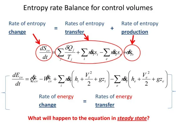
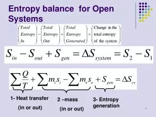
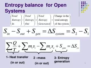
Entropy balance for Open Systems. 1- Heat transfer (in or out). 2 –mass (in or out). 3- Entropy generation. For Steady state Systems. On a rate basis, it becomes. For steady sate process,. For one stream steady sate process,. Entropy balance. Transient. Steady Flow.

E N D
Entropy balance for Open Systems 1- Heat transfer (in or out) 2 –mass (in or out) 3- Entropy generation
For Steady state Systems On a rate basis, it becomes For steady sate process, For one stream steady sate process,
Entropy balance Transient Steady Flow Closed System
An isentropic process is defined as a process during which the entropy remains constant. It helps us in problem solving: The assumption that a process is isentropic, gives us a connection between the inlet and outlet conditions – just like assuming constant volume, or constant pressure
Example (6-5): Isentropic expansion of steam in a turbine Steam enters an adiabatic turbine at 5 MPa and 450oC and leaves at a pressure of 1.4 MPa. Determine the work output of the turbine per unit mass of steam flowing through the turbine if the process is reversible and the change in kinetic and potential energies are negligible.
Example(6-9): Entropy Change of an Ideal Gas Air is compressed from an initial state of 100 kPa and 17oC to a final state of 600 kPa and 57oC. Determine the entropy change of air during this compression process by using (a) property values from the air table and (b) average specific heats. <Answers: a) -0.3844 kJ/kg.K, b) -0.3842 kJ/kg.K> Solution: • Remember, if this were steam, we wouldn’t have to worry about any of these equations. We’d just use the steam tables!!
Example (6-11): Isentropic Compression of an Ideal Gas Helium gas is compressed in an adiabatic compressor from an initial state of 14 psia and 50oF to a final state temperature of 320oF in a reversible manner. Determine the exit pressure of helium. <Answer: 40.5 psia> Sol:
T1 = 450 ºC p1 = 7 MPa p2 = 3 MPa Example (6-18) Steam at 7 MPa and 450 ºC is throttled through a valve to 3 MPa. Find the entropy generation through the process. This is a steady state problem. 0
Example (6-18) (continued) T1 = 450 ºC p1 = 7 MPa h1 = 3287.1 kJ/kg s1 = 6.6327 kJ/kg K Table A-6 To fix state 2, this is a throttling process => h2 = h1 p2 = 3 MPa h2 = 3287.1 kJ/kg s2 = 6.9919 kJ/kg K Table A-6 sgen = Δs=s2-s1 = 6.9919 – 6.6327 = 0.3592 kJ/kg K
Isentropic Efficiencies of Steady Flow Devices • The irreversibilities inherently accompany all actual processes downgrading the performance of devices. • We want to quantify the degree of degradation of energy in these devices. • This is done by comparing our actual processes to the isentropic process (ideal process) • Isentropic efficiency is a measure of the deviation of actual processes from the corresponding idealized ones.
Isentropic Efficiency of Turbines Remember, if KE and PE are ignored in the energy balance equation, then the work is
Example (6-14): Isentropic Efficiency of a Steam Turbine Steam enters an adiabatic turbine steadily at 3MPa and 400oC and leaves at 50 kPa and 100oC. If the power output of the turbine is 2 MW, determine a) the isentropic efficiency of the turbine and b) the mass flow rate of the steam flowing through the turbine. <Answers: a) 66.6%, b) 3.65 kg/s> Sol:
Isentropic Efficiency of Compressors Remember, if KE and PE are ignored in the energy balance equation, then the work is 0.75 < isen,comp 0.85 for Well-designed compressors.
Example (6-15): Effect of Efficiency on Compressor Power Input Air is compressed by an adiabatic compressor from 100 kPa and 12oC to pressure of 800 kPa at a steady rate of 0.2 kg/s. If the isentropic efficiency of the compressor is 80 percent, determine a) the exit temperature of air and b) the required power input to the compressor.
Isentropic Efficiency of Pumps • When the changes in kinetic and potential energies of a liquid are negligible, the isentropic efficiency of a pump defined similarly as
Isothermal Efficiency of Compressors • A realistic model process for compressors that are intentionally cooled during the compression process is the reversibleisothermal process. We define an isothermal efficiency as • Where wt and wa are the required work inputs to the compressor for the reversible isothermal and actual cases, respectively.
A1 A2 Isentropic Efficiency of Nozzles • The objective of a nozzle is to increase the kinetic energy of the gas • Usually, the inlet velocity is low enough that we can consider it to have zero kinetic energy
Isentropic Efficiency of Nozzles Isentropic efficiency of nozzles are usually greater than 90 %.
Example (6-16): Effect Efficiency on Nozzle Exit Velocity Air at 200 kPa and 950 K enters an adiabatic nozzle at low velocity and is discharged at a pressure of 80 kPa. If the isentropic efficiency of the nozzle is 92 percent, determine a) the maximum possible exit velocity, b) the exit temperature, and c) the actual velocity of the air. Assume constant specific heats for air. <Answers: a) 666 m/s, b) 764 K, c) 639 m/s> Sol:
Reversible steady-flow work • In Chapter 3, Work Done during a Process was found to be • It depends on the path of the process as well as the properties at the end states. Work Done during a Process
Work Done During a steady state process In a steady state process, usually there are no moving boundaries • It would be useful to be able to express the work done during a steady flow process, in terms of system properties • Recall that steady flow systems work best when they have no irreversibilities
Consider general form of the Energy Balance for steady flow steady state processes per unit mass basis (KJ/kg) differential form
For incompressible fluids, v is constant, hence If the device does not involves work like nozzles or pipes, Bernoulli’s equation
For devices dealing with compressible fluids, like turbines and compressors, v is not constant, but the KE and PE are negligible. Hence In order to integrate, we need to know the relationship between v and P.
Important observation Note that the work term is smallest when v is small. So, for a pump (which uses work) you want v to be small. For a turbine (which produces work) you want v to be large. Why agas power plant delivers less net work per unit mass of the working fluid than steam power plant? • A considerable portion of the work output of the turbine is consumed by the compressor. • This is one of the reasons for the overwhelming popularity of steam power plant in electric power generation. • What will happen if we don’t condense the steam?
Proof that wrev,out wact,out and wrev,in wact,in Work-producing devices such as turbines deliver more work, and work-consuming devices such as pumps and compressors require less work when they operate reversibly.
Example (6-12): Compressing a Substance in the Liquid vs. Gas Phase Determine the compressor work input required to compress steam isentropically from 100 kPa to 1 MPa, assuming that the steam exists as (a) saturated liquid and (b) saturated vapor at the inlet state. <Answers: a) 0.94 kJ/kg, b) 520 kJ/kg>
Minimizing the Compressor Work • Obviously one way of minimizing the compressor work is to approach an isentropic process. • That is we minimize all irreversibilities (friction, turbulence, non-quasi-equilibrium effects). • But this is limited by economic considerations. • The best way, is to keep the specific volume as low as possible during the compression process. • By cooling it.
Effect of cooling the compressor • To understand how the cooling affects the work, let us consider three processes: • Isothermal process (maximum cooling) • Isentropic process (No cooling) • Polytropic process (some cooling) • Assume also that all three processes • Have the same inlet and exit pressures. • Are internally reversible • The gas behaves as an ideal gas • Specific heats are constants.
1- Isothermal process Consider an ideal gas, at constant T Remember, this is only true for the isothermal case, for an ideal gas
2- Isentropic process Isentropic means reversible and adiabatic (Q=0) i.e. No cooling is allowed Recall from isentropic relations for an ideal gas Rearrange to find v, plug in and integrate Now its “just” algebra, to rearrange into a more useful form
Remember, this equation only applies to the isentropic case, for an ideal gas, assuming constant specific heats
3- Polytropic process Back in Chapter 3 we said that in a polytropic process Pvn is a constant This is exactly the same as the isentropic case, but with n instead of k!!
1- Isothermal process 2- Isentropic process Summary 3- Polytropic process
Let us plot the three processes on a P-v Diagram for the same final and initial pressures The area to the left of each line represents the work, vdP Note, that it takes the maximum work in isentropic compression while it takes minimum work for an isothermal compression
So as an engineer, you should compress gas isothermally, inorder to consume minimum work. However, for a turbine, we need to produce the maximum work. So, a turbine should expand isentropically(diabatically and reversibly). That is why we assume Q = 0 in the 1st low analysis of a turbine.
Multistage compression with inter-cooling • One common way is to use cooling jackets around the casing of the compressor. • However, this is not sufficient in some cases. • Instead, multistage compression is more common, with cooling between steps. • The gas is compressed in stages and cooled to the initial temperature after each stage. • This is done by passing it through a heat exchanger called “intercooler”. • Multistage cooling is attractive in high pressure ratio compression.
Two stage Compressor The colored area on the P- diagram represents the work saved as a result of two-stage compression with inter-cooling.
Minimizing the work input for a two stage Compressor The size of the colored area (the saved work input) on previous slide varies with the value of the intermediate pressure Px. The total work input for a two-stage compressor is the sum of the work inputs for each stage of compression.
The only variable is Px . The Pxvalue that will minimize the total work is determined by differentiating the above expression with respect to Px. And setting the result to zero. This gives That is to minimize the compression work during two stage compression, the pressure ratio a cross each stage of the compressor must be the same.
Example (6-13): Work Input for Various Compression Processes Air is compressed steadily by a irreversible compressor from an inlet state of 100 kPa and 300 K to an exit pressure of 900 kPa. Determine the compressor work per unit mass for a) isentropic compression with k = 1.4, b) polytropic compression with n = 1.3, c) isothermal compression, and d) ideal two-stage compression with intercooling with a polytropic exponent of 1.3. <Answers: a) 263.2, b) 246.4, c) 189.2, d) 215.3 kJ/kg> Sol:
Reducing the Cost of Compressed Air • Skim • Repair Air Leaks • Install High Efficiency Motors • Use a small motor at high capacity, instead of a large motor at low capacity • Use outside air for compressor intake • Reduce the air pressure setting