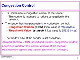
Congestion Control
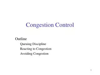
Congestion Control. Outline. Queuing Discipline Reacting to Congestion Avoiding Congestion. Source. 1. 10-Mbps Ethernet. Router. Destination. 1.5-Mbps T1 link. 100-Mbps FDDI. Source. 2. Issues. Congestion: input rate exceeds output rate Avoidance vs Control:

Congestion Control
E N D
Presentation Transcript
Outline • Queuing Discipline • Reacting to Congestion • Avoiding Congestion
Source 1 10-Mbps Ethernet Router Destination 1.5-Mbps T1 link 100-Mbps FDDI Source 2 Issues • Congestion: input rate exceeds output rate • Avoidance vs Control: • pre-allocate resources so as to avoid congestion (avoidance) • control congestion if (and when) it occurs (control) • Underlying service model • best-effort (assume for now) • multiple qualities of service (later)
Framework Source • Flow • sequence of packets sent between source/destination pair • Connectionless flows • maintain soft state (if any) at the routers (not created/removed by signaling) • Connection-oriented flows • State at each router is explicitly allocated for the flow (like virtual circuits) 1 Router Destination 1 Router Source 2 Router Destination 2 Source 3
Taxonomy of schemes • Point of implementation? • router-centric versus host-centric • Resource allocation scheme? • reservation-based: literally reserve resources • feedback-based: the network tells you to go faster/slower • explicit feedback • implicit feedback (TCP) • Rate control Method? • window-based (TCP) • rate-based
Evaluation Criteria • Fairness – allocate resources fairly among flows. • Power (ratio of throughput to delay) • If you increase load • Packet losses increase • Queuing delay increases Throughput/delay Optimal Load load
Flow 1 Flow 2 Round-robin service Flow 3 Flow 4 Queuing Discipline (Scheduling) • First-In-First-Out (FIFO) • does not discriminate between traffic sources (one queue for all) • Fair Queuing (FQ) • explicitly segregates traffic based on flows (how?) • ensures no flow captures more than its share of capacity • variation: weighted fair queuing (WFQ) • FQ problems: • How to differentiatebetween flows • Must considervariable packet size
Fair Queuing Algorithm • In FQ, there are two “servers” (or systems) • The real system • This is the real router with a real output link and the real flows arriving into the router • The “fake” system • It does not exist • Has the same output link capacity as the real system • Has the same input flows (with the same packets) as the real system • However, it is a “bit-by-bit” (fluid) server, not a packet server.
The “fake” system • Bit-by-bit round-robin server • not real service!, i.e. fake! • Suppose a fake clock ticks each time a bit is transmitted from every active flow (i.e., after each round) • i.e., it is not a real-time clock • Let Lf,i denote the length of f.i, i.e., ith packet of flow f • Let Sf,i denote the fake time when start to transmit packet i • Let Ff,i denote the fake time when finish transmitting packet i (regardless of other flows in the system) Ff,i = Sf,i + Lf,i
Computing Sf,i • When does the (fake) server start to transmit first bit of packet f,i? i.e., what is Sf,i? • if when f,i arrives, server has not finished packet f,(i -1) from f, then immediately after last bit of f,(i – 1), i.e., Sf,i = Ff,i-1 • if no current packets queued for this flow, then start transmitting f,i when it arrives, i.e., Sf,i = Vf,i • where Vf,i is the fake time when the packet arrives • Thus: Ff,i = Sf,i+ Lf,i = MAX (Ff,i - 1, Vf,i) + Lf,i
Calculating V • V is not “real-time” • It grows depending on the number of backlogged flows (flows whose queue is not empty) • Output channel rate is constant • We tick after transmitting one bit of each flow • If more flows, then it takes more time to transmit one bit of each flow (the round takes more time) • Hence, the number of queued flows dictates how fast (with respect to real-time) V grows.
Virtual time rate changes with backlogged flows V(t) Virtual time of real time t Real time Backlogged flows at fake server increased Backlogged flows at fake server decreased
Calculating V (continued) • Actually, the rate of growth of V “changes” when the set of backlogged flows (i.e. with non-empty queue) changes. • The rate of growth increases when a flow is no longer queued • The rate of growth decreases when a the queue of a flow becomes non-empty • It is somewhat of a mess to compute it • We will cover all the gory details soon …
“Real” FQ Server • Packets are sent out according to which one would exit the fake server first. (try to mimic the fake server) • When a packet Pf,iis received • Compute the value Ff,i (this depends on V) • Insert packet into a priority queue, ordered by F value • When the output channel becomes idle • Retrieve the packet from the priority queue with least F value • I.e. the one that would exit first from the fake server. • Transmit this packet.
FQ Algorithm limitations • Want to emulate the behavior of the bit-by-bit server as much as possible • We want each packet to exit from the real server no later than it exits from the bit-by-bit server • However, not perfect: can’t preempt current packet, so exit time may be greater • Example Flow 1 Flow 2 Flow 1 Flow 2 Output (arriving) (transmitting) Output F = 10 F = 10 F = 8 F = 5 F = 2 (a) What you want (b) What you may get instead
TCP Congestion Control • Idea • assumes best-effort network (FIFO or FQ routers) • each source determines network capacity for itself • uses implicit feedback • ACKs pace transmission (self-clocking) • Challenge • determining the available capacity in the first place • adjusting to changes in the available capacity
Data Data Data Data Data Data Data Data Data Data Data Data Data Data Data Data ACK ACK ACK ACK ACK Sender Receiver Sender Receiver • Advantages: • More frames in pipe • Less time overall Time Sliding Window Protocol (review) ACK ACK ACK ACK
Message Sequence Numbers • TCP transfers a stream of bytes to the destination • data(x): • x is the sequence number, assume the message is L bytes long • x corresponds to the stream byte number of the first byte in the message • The next data message has sequence number x+L • ack(y): • Ack’s are cumulative, it indicates the receiver has received bytes 0 .. y-1, and is expecting byte y x x+(L-1)
Variables of Sender and Receiver Sender • Every byte i, i ≤ LastByteAcked, has been acked • Every byte i, i ≤ LastByteSent, has been sent • Bytes in between LastByteAcked and LastByteSent (blue) have been sent but no ack received yet • Every byte i, i < NextByteExpected, has been received. • LastByteAcked ≤ NextByteExpected – 1 ≤ LastByteSent (why?) • If receiver receives data(x), where x > NextByteExpected, it either throws it away (unlikely) or buffers it (it was received out of order) LastByteAcked LastByteSent Receiver NextByteExpected
Seq=92 timeout time TCP: retransmission scenarios Host A Host B Host A Host B Seq=92, 8 bytes data Seq=92, 8 bytes data Seq=100, 20 bytes data ACK=100 timeout X ACK=100 ACK=120 loss LastByteAcked = 99 Seq=92, 8 bytes data Seq=92, 8 bytes data LastByteAcked = 119 ACK=120 Seq=92 timeout ACK=100 LastByteAcked = 99 LastByteAcked = 119 lost ACK scenario premature timeout time
TCP retransmission scenarios (more) Host A Host B Seq=92, 8 bytes data ACK=100 Seq=100, 20 bytes data timeout X loss LastByteAcked = 119 ACK=120 time Cumulative ACK scenario: ack loss not detected
Sender (congestion) Window Sender • You should already know how the sliding window protocol works (with cumulative ack’s) • LastByteSent – LastByteAcked ≤ SenderWindow • The sender window is also known as the “congestion” window if it is allowed to change size over time (more on this soon) • The sender window limits how many bytes from the sender can be in the network at any moment in time. LastByteAcked LastByteSent
Simplifying Assumptions • We generate an ack for every data message received • The sender has always data to send.
Self-clocking or ACK Clock (picture of bottleneck router link) • Self-clocking systems tend to be very stable under a wide range of bandwidths and delays. • The principal issue with self-clocking systems is getting them started. Pr Pb Receiver Sender Ab As Ar
Throughput • If the window is W • And if the round-trip delay is D • In general, what is the throughput of the sliding window protocol (TCP or any other sliding window)? • (assuming the “bottleneck” link is not the first link of the host) Source Router Router Router Router Dest One of these routers is the “bottleneck” router, whose link is the slowest (or busiest)
Window vs Round-Trip-Time How would you adjust the window to keep it close to Wopt? Wopt = optimum window = baseRTT * Bandwidth
Window vs Throughput How would you adjust the window to keep it close to Wopt?
TCP • TCP does NOT know what baseRTT is (the network does not tell it) nor the bandwidth! • So, it CAN’t compute Wopt! • It must therefore act “blind”
Additive Increase/Multiplicative Decrease • Objective: adjust to changes in the available capacity • New state variable per connection: CongestionWindow • limits how much data source has in transit • (LastByteSent - LastByteAcked) ≤ CongestionWindow • Idea: • increase CongestionWindow when congestion goes down • decrease CongestionWindow when congestion goes up
TCP congestion states: • Congestion “avoidance” – Normal operation, no congestion has been detected • Congestion “control” – Fix the fact that congestion has occurred
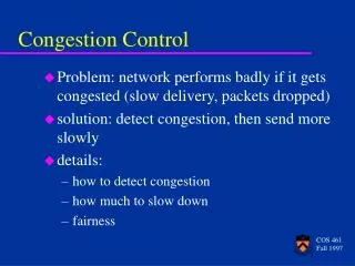
Detecting congestion • Question: how does the source determine whether or not the network is congested?
Timeout congestion • Answer: a timeout occurs • timeout signals that a packet was lost • packets are seldom lost due to transmission error • lost packet implies congestion
Detecting the absence of congestion • How does TCP detect that the network is NOT congested? (i.e. that its window size is not bigger than what it should)
Answer • It doesn’t !!!! • It just assumes there is no congestion starting to occur
Source Destination … AIMD • Algorithm • increment CongestionWindow by one packet per RTT (linear increase, i.e. we are in congestion avoidance) • divide CongestionWindow by two whenever a timeout occurs (multiplicative decrease, i.e. begin congestion control) • Linear increase in practice: increment a little for each ACK Increment = MSS * (MSS/CongestionWindow) CongestionWindow = CongestionWindow + Increment (MSS = TCP’s maximum segment (packet) size)
AIMD (cont) • Trace: sawtooth behavior 70 60 50 40 Window KB 30 20 10 1.0 2.0 3.0 4.0 5.0 6.0 7.0 8.0 9.0 10.0 T ime (seconds)
Initial window value • Initially, you don’t know the network capacity • What then should be the value of congwin? • Perhaps a value hard-coded in the program: • E.g., always start W = 20KB • Problems: • If congwin is too small, we waste bandwith • Takes a long time for congwin to grow using cong. avoidance • If congwin is too big we cause congestion • Dumping congwin bytes in the network, at once, even if W is the right value, may cause congestion.
Source Destination … Slow Start • Objective: determine the available capacity in the first place • Idea: • begin with CongestionWindow = 1 packet • double CongestionWindow each RTT (increment by 1 packet for each ACK)
When to switch to linear? There is no good answer when you startup a connection cwnd time
Slow Start (cont) • Exponential growth, but slower than all at once • Used… • when first starting connection • when connection goes dead waiting for timeout and we go into congestion control (see next slides) • By the way, how many of your packets are in the network after you receive an ack for a retransmitted packet?
Congestion Control • After a timeout, we are in “congestion control” mode • set slow-start thresholdSSThresh to CongestionWindow/2 • set CongestionWindow to 1 • Allow CongestionWindow to grow exponentially using “slow start” until it reaches the SSThresh • Then, continue with additive increase of CongestionWindow (i.e., back to congestion avoidance)
14 12 10 8 congestion window size (segments) 6 4 2 0 1 2 3 4 5 6 7 8 9 10 11 12 13 14 15 Transmission round Window size over time cwnd time
Fast Retransmit • Problem: coarse-grain TCP timeouts lead to idle periods • Fast retransmit: use duplicate ACKs to trigger retransmission (3 of them in case there is reorder) Sender Receiver Packet 10 Packet 20 ACK 20 Packet 30 ACK 30 Packet 40 ACK 30 Packet 50 Packet 60 ACK 30 ACK 30 Retransmit packet 30 ACK 70
Slow start or not? • After a fast retransmission – • Do a slow start? (set the CongestionWindow to 1 and increase exponentially up to Thresh) • (again, how many packets are in the network after we receive an ack for the retransmitted packet?) • Or not? (Fast Recovery, details later…) • Go “directly” to half the previous congestion window • Avoid the slow start • More details on this later … • The above depends on the version of TCP
TCP Tahoe and TCP Reno(for single segment losses) Reno cwnd Tahoe Does slow start time cwnd Does “fast recovery” time