Download
1 / 16
160 likes | 293 Vues
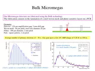
The Micromegas project focuses on upgrading muon chambers for the SLHC at ATLAS to enhance performance. Objectives include replacing existing chambers in high-rate areas, integrating triggering and measurement functions into single chambers, and developing large-area detectors (1m x 2m). With a target efficiency of over 98% and a time resolution of less than 0.5 ns, this technology promises improved precision. Ongoing R&D with 12 participating institutes will establish best practices and evaluate triggering solutions, aiming for robust performance in high-radiation environments.

E N D
Micromegas for ATLAS R&D for an upgrade of muon chambers for the SLHC Arizona, Athens (U, NTU, Demokritos), Brookhaven, Bucharest, CERN, Naples, St. Peterburg, Thessaloniki, Seattle, South Carolina J. Wotschack/CERN
The scope • LSLHC = ~10 x LLHC; t(bunch crossing) = 50 ns • Replace muon chambers in regions with highest counting rates (few kHz/cm2 @ L=1035cm-2s-1, mostly from neutrons and ’s) • Inner and part of middle layer of end-cap chambers (100 – 200 m2) • At present separate precision and trigger chambers (MDTs, CSCs, TGCs) • Combine trigger & precision measurement function in single chamber J. Wotschack/CERN
Micromegas as candidate technology Attractive features • Can combine triggering and tracking function • Required performance • Efficiency > 98% • sp≈100 m (track<45 degr) • Good double track resolution • t < 5 ns • Potential for going to larger areas: 1 m x 2 m J. Wotschack/CERN
ATLAS Micromegas R&D Collaboration Evaluate possible use of micromegas for ATLAS muon chamber upgrade programme • EoI submitted in February 2007 to ATLAS Upgrade Office • Proposal submitted in June 2007 • 12 participating Institutes so far; with growing interest ... • Regular weekly meetings at CERN since February. • TWiki page with agenda, contributions and minutes of all meeting plus other useful information and links: https://twiki.cern.ch/twiki/bin/view/Atlas/MuonMicromegas J. Wotschack/CERN
Goals • Phase I: Build and evaluate small prototype(s) based on micromegas technology to • get familiar with technology • demonstrate required performance Decide on • Operating parameters (gas, gas gain, HV, etc...) • Readout pattern & electronics • Phase II: Develop techniques for the construction of large-size detectors (1m x 2m) J. Wotschack/CERN
Prototype layout • Board Layout (not to scale) 450mm x 350mm active area Several strip patterns (250, 500, 1000, 2000 µm pitch; long, short) • Three variants with same board layout: • Standard mesh (CERN) • Segmented mesh (CERN) for trigger + 2nd coordinate Novel technology • Standard mesh + resistive layer on the read-out strips larger footprint (BNL) • Drift gap: 2–5 mm J. Wotschack/CERN
The mesh(es) Mesh–readout electrode distance: 128 µm Prototype 1 (P1) Homogeneous stainless steel mesh 450 lines/inch = 56 µm pitch Prototype 2 (P2) Unidirectional stainless steel/plastic mesh 200 lines/inch = 127 µm pitch J. Wotschack/CERN
The first boards P1(homogeneous mesh): Done at CERN/TS-DEM; mechanical integration this/next week P2(segmented mesh): in production Long strips Short strips HV + signal connection for segmented mesh (groups of 100 wires) J. Wotschack/CERN
Rpolar. strip Preamp C~100pF Readout electronics 2007 • ALICE PHOS electr. + DAQ chain (H. Muller) • 128 channels (tested) • Spark protection with diodes tested • Strip signals only (neg.) • BNL 32-chan. chip • 128 channels • Bi-polar (strips & mesh) • Standard readout H. Muller Readout elx components dimensioned ALICE online histogramming available J. Wotschack/CERN
Plans 2007 • Oct/Nov 2007: test beam (H8) • Two prototypes (possibly more from BNL) • Three (non-flammable) gas mixtures: • Ar:CO2 (80:20); Ar:CF4 (85:15); Ar:Ne:CF4 (45:45:10) • Learn how to work with micromegas • Evaluate different strip patterns • Study performance as function of track impact angle • Vary drift gap (2 – 5 mm) • Target for end 2007/beg 2008: • Establish base-line readout strip pattern • Establish base-line gas and detector parameters J. Wotschack/CERN
Plans for 2008+ • Prototype construction • Possibly 2nd ‘small’ prototype, based on 2007 experience • Pursue segmented mesh option, optimise amplification gap size • Main emphasis on developing technology for building large-scale micromegas (1m x 2m) • Read out electronics • Move to custom solution for micro pattern readout electronics, hope to profit from ongoing R&D activities in the field • Equip larger areas of prototype chambers • Evaluate triggering solutions, possibly adaptation to existing ATLAS trigger infrastructure • Ageing tests under high photon irradiation (in GIF ?) • ATLAS system integration + performance studies J. Wotschack/CERN
Interest in common R&D • Technology for large-area micromegas • Production facilities for large-area board production • Readout electronics • Standardized test procedures (common lab) • Simulation • High rate/ageing studies • Micromegas in large systems J. Wotschack/CERN
Back-up slides J. Wotschack/CERN
ATLAS: average single count rates for L=1034 cm-2s-1 J. Wotschack/CERN
Gas simulation studies: K.Mermigka + R.Veenhof J. Wotschack/CERN
Transverse diffusion Drift velocity Ar 45% Ne 45% CF4 10% Ar 85% CF4 15% 700 V 600 V 500 V 400 V 300 V 200 V 100 V 700 V 600 V 500 V 400 V 300 V 200 V 100 V Gas gain J. Wotschack/CERN