Download
1 / 22
220 likes | 514 Vues
Carbon sputtering technology for ATLAS MicroMEGAS resistive. Atsuhiko Ochi 1 , Yasuhiro Homma 1 , Tsuyoshi Takemoto 1 , Fumiya Yamane 1 , Yousuke Kataoka 2 , Tatsuya Masubuchi 2 , Yuki Kawanishi 2 , Shingo Terao 2 Kobe University 1 , Univ. Tokyo ICEPP 2.

E N D
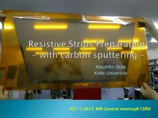
Carbon sputtering technologyfor ATLAS MicroMEGAS resistive Atsuhiko Ochi1, Yasuhiro Homma1, Tsuyoshi Takemoto1, Fumiya Yamane1, Yousuke Kataoka2, Tatsuya Masubuchi2, Yuki Kawanishi2, Shingo Terao2 Kobe University1, Univ. Tokyo ICEPP2 06/02/2014 13th RD51 meeting@ CERN
Requirements for ATLAS NSW MM • High position resolution for one dimension • <100 μm for eta direction.(Resolution of a few cm is allowed for second coordinate.) • Tolerant for high rate HIP particles • ~ 5kHz/cm2 • Resistive layer should be formed as strips • Resistivity: ~20MΩ/cm • To protect from spark • Mass production should be available, with large size (1m) • ~2000 board should be produced in half year. • Low cost Mesh (GND) +HV A. Ochi, 13th RD51 Meeting
Two option for resistive electrodes • Screen printing • Already several prototypes (@ CERN and Japan) has been produced. • Made from carbon loaded polymer. • Large size (>1m2) is available • 400 μm pitch was available for MAMMA production. • Carbon sputtering with liftoff process • New technique.(Since 2013) • Fine pattern (~10μm) is available. • Large size (>1m2) is available in industrial facilities. • Production quality is very well. • It is not affected by production environment A. Ochi, 13th RD51 Meeting
Liftoff process using sputtering Photo resist (reverse pattern of surface strips) • Very fine structure (a few tens micro meter) can be formed using photo resist. (same as PCB) • Surface resistivity can be controlled by sputtering material and their thickness @PCB company (Laytech inc.) Substrate (polyimide) Metal/Carbon sputtering @Sputtering company (Be-Sputter inc.) Substrate (polyimide) Developing the resists @PCB company (Laytech inc.) Substrate (polyimide) A. Ochi, 13th RD51 Meeting
Prototype of small MicroMEGAS Carbon (300-600Å) • June, 2013 – bulk MM • Surface resistivity: 10MΩ/sq. • With 300Ǻ carbon + 50Ǻ W • November, 2013 – floating mesh • Surface resistivity: 500kΩ/sq. • With 3600Ǻ carbon • The readout board consists of • Readout strips (Rigid PCB). • Resistive strip foil (Polyimide film). • Fine strip pitch of 200 μm is formed on 25μm polyimide foil. • Substrate thickness : 60 μm. Tungsten (10-50Å) Substrate (polyimide) Mesh Resistive strips (sputtered) Pillar Flexible foil (polyimide) 25μm Bonding film 35μm Readout strips Rigid PCB (epoxy) A. Ochi, 13th RD51 Meeting
Fast neutron test • Beamtests for sputtering MPGD • Gain curve of 5.9 keV X-ray. • Drift = -300V • Drift spacing: 5mm • Gas: Ar(93%) + CO2(7%) • Fast Neutron test for spark probability • @Kobe Univ. • 17-23 Jun. 2013 • 20-27 Jan. 2014 • HV current log under intense neutron. • Neutron intense : ~ 105 cps/cm2. • 0.01V correspond to 1 μA • ~600nA of base current was found while beam ON. Very preliminary 1 μA Be(d, n)B A. Ochi, 13th RD51 Meeting neutron -HV (~-300V) Drift Anode = ~500V A
After sparks by neutrons • No damage is observed on the resistive strips after neutron test A. Ochi, 13th RD51 Meeting
Charged particle tracking • Cosmic test using 4 MMs • At Kobe Univ, Sept. 2013 • 1.4GeV electron beam • At Spring-8 BL33 beamline, Nov. 2013 SRS system MM x 6 + Scintillators + APV25 x 12 A. Ochi, 13th RD51 Meeting
Further improvements and tests for carbon sputtering • Requirements for carbon strips • Resistive control • 20 MΩ/cm is required • It correspond to 600kΩ/sq. for 300μm line width. • Our first prototype has 10MΩ /sq. • Thicker carbon sputter is required • Long time stability of resistivity • The resistivity of early prototypes were growing up as time goes on (~2%/day) • It was thought that the oxidation of metal (tungsten layer) • Is the carbon sputtering without metal layer possible? • Mechanical / chemical robustness test • Peeling off property (cross cut method) • Resistive stability against the bending of the foil • Chemical stabilities • For alkali and acid, used for PCB process. A. Ochi, 13th RD51 Meeting
Resistivity and it’s stability • Resistivity dependence on carbon thickness • 300Ǻ 2GΩ/sq. • 3600Ǻ 500kΩ/sq. • Conductivity is not proportional to the thickness (t < 1000Ǻ) • At t > 1000Ǻ, good reproducibility found • New prototype:(delivered at September) • Carbon, 3600Ǻ • Surface resistivity ~ 500kΩ/sq. • No time variation founds after several days from sputtering Carbon (3600Å) Substrate (polyimide) Preliminary Surface Resistivity [MΩ/sq.] No time variation founds Cupper thickness [Ǻ] day A. Ochi, 13th RD51 Meeting
Mechanical robustnessfor thick sputtering carbon Cross-cut test(JIS k5400-8.5) • Adhesion test • Cross-cut test(JIS k5400-8.5 standard, similar to the ISO 2409) • No peeled carbon founded • Bending test • Bending diameter > 4cm No resistivity change found • Jackknife bending Conductivity is lost • Bending diameter = 1.2cm Outer wrap: resistivity is increased 10-20% Inner wrap: no resistivity change 0.51MΩ/sq. 0.57MΩ/sq. (+12%) Making cut lines as grid (11 x 11, 1mm pitch) Tape up the foils strongly Peel off the tape at once After bending Before bending Observe the tape and foils. 0.44MΩ/sq. 0.44M Ω/sq. (0%) Before bending After bending A. Ochi, 13th RD51 Meeting
Chemical robustnessfor new sputtering carbon • Acid and alkali for PCB processing • Hydrochloric acid • Nitric acid • Sulfuric acid • Sodium carbonate No damage on sputtered carbon • Sodium hydroxide No damage for short dip Peeling is found after 90 minutes dipping • Almost all process of PCB production will not affect to the sputtering carbon A. Ochi, 13th RD51 Meeting
Prototype of large MMs Readout board • We can divide the production process of resistive strip from that of readout board. • Resistive strip is formed on thin foil • We don’t need fine alignment between resistive strips and readout strips. • Dividing those processes will make the yield of production growing up. • We are preparing the large resistive strip foil. • Size of foils: 500mm x 1000mm • 4 foils are need for a quadruplet • 8 Foils (4 foils and 4 spare) were delivered to us at 25th October. • Some basic resistive parameters are checked. • Those have been already come to CERN Resistive Strip foil A. Ochi, 13th RD51 Meeting
For patterning process: Laytech inc. • PCB company • They are expert for FPC (Flexible Printed Circuit) production. • Liftoff is basic process for FPC production Electro forming machines Etching machines Exposure machines in clean room A. Ochi, 13th RD51 Meeting
Sputtering facilities • Large size sputtering is available • 4.5m x 1m for flexible film Be-Sputter Co. Ltd. (Kyoto Japan) A. Ochi, 13th RD51 Meeting Sample Vacuum chamber (with Ar gas) Rotating drum 4.5 m round Sputtering target
Large resistive strip foil 866.4mm 425.3mm A. Ochi, 13th RD51 Meeting
Enlarged picture of resistive strip foil 10 mm 0.3 mm 1 mm A. Ochi, 13th RD51 Meeting
Resistivity check B • We have no systematic way for resistivity test yet, so these results are based on rough measurements. • However, we have check surface resistivity on several points for 8 foils as figure. • The prove has about 2cm width. • Distance between proves are, A,B,C: 1.5-2.5 cm, D: 30 cm, E: cross over a center line. • “Inf” means more than 50MΩ. C A D E Unit: MΩ A. Ochi, 13th RD51 Meeting
Resistivity check • Resistivity from edge to lattice point (5cm x 5cm) were measured (by Fabien Kuger). Foil: No.1, Unit: MΩ A B C D E F G A. Ochi, 13th RD51 Meeting
Comparison of different foils • Variability of ~ 30% were found for different foils • Reducing it is one of future issue A. Ochi, 13th RD51 Meeting
With readout board • 4 foils are attached to readout board successfully (at Rui’s workshop) • For making quadruplet prototype (MSW) • Resistivity did not change after gluing • Pillars will be formed soon A. Ochi, 13th RD51 Meeting
Conclusion • Sputtering technology is very promising for making MPGD resistive electrodes • Fine structure (~10μm) • Large area ( a few meter) • Prototype of MicroMEGAS using sputtered resistive electrodes were produced and tested. • It works as same as conventional resistive strip MicroMEGAS • Gain curve, operation in HIP were tested. It’s OK. • Carbon sputtering process is improved for ATLAS MicroMEGAS • Appropriate resistivity ~ 500kΩ/sq with thick (3600Ǻ) sputtering. • Good mechanical/chemical properties • Large resistive strip foils (0.5m x 1m) are produced for functional prototype (MSW). • Qualitative resistivity check is ok. • The foils are already put on the readout board. • No resistivity change found before/after foil gluing. A. Ochi, 13th RD51 Meeting