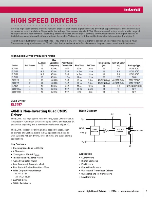
High-Speed Serial Link
High-Speed Serial Link. Deog-Kyoon Jeong Seoul National University dkjeong@ee.snu.ac.kr. Outline. Introduction High-speed I/O overview Hot design issues Design examples Summary. 10 4. 10 8. 10 7. 10 3. 10 6. 10 5. Gates density. CPU performance. 10 2. 10 4. 10 3. 10 1. 10 2.

High-Speed Serial Link
E N D
Presentation Transcript
High-Speed Serial Link Deog-Kyoon Jeong Seoul National University dkjeong@ee.snu.ac.kr
Outline • Introduction • High-speed I/O overview • Hot design issues • Design examples • Summary
104 108 107 103 106 105 Gates density CPU performance 102 104 103 101 102 101 100 100 1996 2000 1992 2004 1996 2000 1980 1984 1988 1992 2004 1980 1984 1988 Introduction • Moore’s law • Performance & density improvement in digital system
104 108 107 103 106 105 Gates density CPU performance 102 104 103 Memory access Signal pins 101 102 101 100 100 1996 2000 1992 2004 1996 2000 1980 1984 1988 1992 2004 1980 1984 1988 Introduction • Moore’s law Growing gap limits system performance!!
Digital System Performance • Performance bottleneck • The cost of arithmetic operation is cheap now Computation - bound Communication - bound “Pentium 4” 20 ~ 30 cycles / Arithmetic operation 500 ~ 600 cycles / DRAM access “Pentium Pro” 10 ~ 20 cycles / Arithmetic operation 70 cycles / DRAM access
Computing System • High-speed I/O is needed everywhere CPU North Bridge Display Graphic Memory Long distance Disk South Bridge Local I/O Switch LAN SAN
Group data (Bus) Source synchronous Matched trace Parallel Bus Data Core I/O I/O Core Clock Serial Link Serial Data Core I/O I/O Core Parallel Bus & Serial Link • Single trace • Plesiochronous • Clock embedded in data • Clock & data recovery
Parallel vs. Serial World is moving toward “serial link” or “serial-link-like parallel bus” !!
Transmitter PCS Serializer Framer Channel PLL Receiver Deserializer PCS Deframer Clock recovery Serial Link Architecture Transmitter + Receiver = Transceiver
CKi ( fin ) Vctr error Phase Detector Loop- Filter Voltage-Controlled Oscillator CKo ( fout ) M Link Component • Phase-locked Loop (PLL) • Frequency multiplication: fout = M·fin • Jitter filter • Zero-delay buffer
Termination ( R = Z0 ) VTT VRR Z0 Channel Z0 To CDR Driver DC block Limiting amp Link Component • High-speed, low voltage swing interface • Usually, differential • Small swing - ~ several hundreds mV
Do Decision circuit Di CKr error Vctr NRZ Phase Detector Loop- Filter Voltage-Controlled Oscillator 0 1 1 0 1 0 0 1 0 0 0 Link Component • Clock & data recovery (CDR) circuits Di CKr Do
Link Performance Metric • Eye diagram & jitter Tbit Random bit sequence Timing uncertainty : Jitter Tbit Eye diagram Ideal Realistic Jitter histogram
Link Performance Metric • Eye diagram example – Near end & far end Framer PLL Channel Deframer Clock recovery
Link Performance Metric • Bit-error rate (BER) • In most serial link standards, BER < 10-12 is specified Eye diagram Jitter PDF =f(x) Jitter histogram Bit error!! Recovered clock
High-Speed Link Standards HyperTransport XDR DVI RDRAM PCI Express CPU LVDS North Bridge Display Graphic Memory SATA Disk South Bridge Local I/O Ethernet Switch LAN SAN Fibre Channel SONET /SDH InfiniBand
Industry Roadmaps Year 2005, world is here!! VGA UXGA SXGA DVI FC-PI-1 FC-PI-2 10GFC Fibre Channel PCIe1.0 PCIe2.0(?) PCI Express Gen1 Gen2 Gen3 SATA OC-12 OC-48 OC-192 OC-768 SONET/SDH Fast Ethernet Gigabit Ethernet 10G Ethernet Ethernet Data-rate XAUI 1G 10G 100G 0.1G
Digital Visual Interface (DVI) • PC display – CRT (analog) LCD (digital) • DVI – Digital Visual Interface Analog Digital
TMDS encoder TMDS decoder Graphic controller Display controller PLL PLL Digital Visual Interface (DVI) • TMDS • Transition minimized differential signaling • EMI reduction
High Definition Multimedia Interface (HDMI) • HDMI • High-definition multi-media interface • Digital video + multi-channel audio interface for consumer electronics • Compatible with DVI
Serial ATA (SATA) • Next generation ATA bus within PC box • Eliminates fat ATA cables • Point-to-point connection – 1.5G/3G/6G Parallel ATA cabling Serial ATA cabling
Transceiver Chip Design • Technology • CMOS, InP, GaAs, SiGe, BiCMOS … • CMOS will be the eventual winner – Low cost, high-integrity • Speed • Power consumption • Area • Level of integration • Mixed-signal SoC – Serial link interface + digital circuitry Trade-off!!
Hot Design Issues • CMOS serial link transceiver Framer PLL Deframer Clock recovery
Hot Design Issues • CMOS serial link transceiver High-speed CMOS circuits - Logic gates, analog buffer Framer PLL Channel loss compensation - Equalizer Precise-timing generation - High-frequency, low jitter PLL Deframer High-performance CDR - High-speed NRZ PD - Various CDR architectures Clock recovery
CKi ( fin ) Vctr error Phase Detector Loop- Filter Voltage-Controlled Oscillator CKo ( fout ) M Precise Timing generation • VCO noise PLL jitter Data eye jitter • Low noise, high-frequency VCO is required
Ring oscillator LC tank oscillator Parasitic resistance Td = C·V / I On-chip spiral L On-chip varactor Negative gm M stages 1 = 1 f = f 2 MT p 2 LC d var Voltage-Controlled Oscillator
CMOS logic Current-mode logic (CML) • R • R + L • R + T-coil PMOS Pull-up ZL Complementary NMOS Logic NMOS Pull-down High-Speed CMOS Circuits • High-speed logic gates
Normal Shunt peaking Shunt series peaking Shunt double- series peaking Shunt peaking Series peaking Series peaking High-Speed CMOS Circuits • High-speed buffer with on-chip inductor • Shunt peaking – Inserts a zero at high frequency • Series peaking – Isolates the buffer output node from load capacitance
D Q D Q High-Speed CDR – NRZ PD • Hogge phase-detector – Linear PD • Full-rate operation • Matched up/down when locked – Less noisy Phase error – Clock early D UP CK A DN A D B B UP CK DN Very short pulse!! Area difference Phase error
B DN Clock late Clock early A D UP D Q D Q D0 D1 D0 D1 CK A B T A T B T UP D Q D Q DN High-Speed CDR – NRZ PD • Alexander phase-detector – Binary PD • With multi-phase clock – Time interleaving • Bang-bang control – Noisy
High-Speed CDR – Architectures • PLL-based CDR • 1 PLL / channel – Precise phase control • Suitable for high-speed, high-performance system Do Decision circuit Either linear or binary Di CKr error Vctr NRZ Phase Detector Loop- Filter Voltage-Controlled Oscillator
Channel Loss • Band-limited channel • Bonding wire, PCB trace, connector, cable … • Skin effect • Dielectric loss
Amplitude 0 0 0 1 0 1 1 1 4TB -4TB -3TB -2TB -TB 0 TB 2TB 3TB Time Channel Loss Effect • Inter-symbol interference (ISI)
Without pre- emphasis With pre- emphasis Channel Loss Compensation • TX – Pre-emphasis
Continuous time equalizer Din Dout High-pass filter Capacitive degeneration g Channel Loss Compensation • RX – Equalization
Design Examples • 40Gbps transmitter • Process – 0.13 CMOS • Power – 2.8W • Area – 2.5 3.6 mm2 • Features • 20G standing-wave VCO • Shunt-double series peaking at 10/20/40G buffers • Active feedback at 20G divider • 410 on-chip spiral inductors
Design Examples • 40G transmitter – Standing wave VCO Varactors
Design Examples • 40G transmitter – test results 25ps Test chip
Design Examples • Features • 10G LC-tank VCO • PLL-based 10G CDR • DLL-based quad 3.125G CDR (XAUI) • Integrated with digital control core • 10G Ethernet PHY with XAUI interface • Process – 0.13 CMOS • Power – 900mW • Area – 5 5 mm2
Design Examples • 3.5G continuous time adaptive equalizer • Process – 0.18 CMOS • Area – 0.48 0.73 mm2 • Power – 80mW @ 3.5G • Features • ~ 3.5G – Adaptive mode • ~ 5G – Manual mode Cable input Cable output Equalizer output
Summary • Now, digital system performance is bounded by system I/O bandwidth • In industry, serial link I/O is going mainstream • Toward low-cost, high-bandwidth system I/O, we should overcome several physical limitations such as • Jitter & noise • Channel loss • Device speed