Understanding Transformations and Local Illumination in 3D Graphics
This comprehensive guide explores the fundamentals of transformations in 3D graphics, including rigid, affine, and projective transformations. It examines the principles of linearity and the application of homogeneous coordinates for translating and scaling objects. The tutorial delves into the importance of local illumination and shading techniques, highlighting the Bidirectional Reflectance Distribution Function (BRDF). With practical examples for ray tracing and transforming normals, readers will gain valuable insights into combining transformations and enhancing their 3D scenes.


Understanding Transformations and Local Illumination in 3D Graphics
E N D
Presentation Transcript
Last Time? • Transformations • Rigid body, affine, similitude, linear, projective • Linearity • f(x+y)=f(x)+f(y); f(ax) = a f(x) • Homogeneous coordinates • (x, y, z, w) ~ (x/w, y/w, z/w) • Translation in a matrix • Projective transforms • Non-commutativity • Transformations in modeling
Today • Intro to Transformations • Classes of Transformations • Representing Transformations • Combining Transformations • Transformations in Modeling • Adding Transformations to our Ray Tracer • Local illumination and shading
Why is a Transform an Object3D? • To position the logical groupings of objects within the scene
Recursive call and composition • Recursive call tree: leaves are evaluated first • Apply matrix from right to left • Natural composition of transformations from object space to world space • First put finger in hand frame • Then apply elbow transform • Then shoulder transform • etc.
Today • Intro to Transformations • Classes of Transformations • Representing Transformations • Combining Transformations • Transformations in Modeling • Adding Transformations to our Ray Tracer
Incorporating Transforms • Make each primitive handle any applied transformations • Transform the Rays Sphere { center 1 0.5 0 radius 2 } Transform { Translate { 1 0.5 0 } Scale { 2 2 2 } Sphere { center 0 0 0 radius 1 } }
Primitives handle Transforms • Complicated for many primitives r minor r major Sphere { center 3 2 0 z_rotation 30 r_major 2 r_minor 1 } (x,y)
Transform the Ray • Move the ray from World Space to Object Space r minor r major (x,y) r = 1 (0,0) World Space Object Space pWS = M pOS pOS = M-1 pWS
Transform Ray • New origin: • New direction: originOS= M-1originWS directionOS= M-1 (originWS+ 1 * directionWS) - M-1 originWS directionOS= M-1directionWS originWS directionWS qWS = originWS + tWS * directionWS originOS directionOS qOS = originOS + tOS * directionOS World Space Object Space
Transforming Points & Directions • Transform point • Transform direction Homogeneous Coordinates: (x,y,z,w) w = 0 is a point at infinity (direction) • With the usual storage strategy (no w) you need different routines to apply M to a point and to a direction
What to do aboutthe depth, t If M includes scaling, directionOS will NOT be normalized • Normalize the direction • Don't normalize the direction
1. Normalize direction • tOS≠ tWS and must be rescaled after intersection tWS tOS Object Space World Space
2. Don't normalize direction • tOS=tWS • Don't rely on tOS being true distance during intersection routines (e.g. geometric ray-sphere intersection, a≠1 in algebraic solution) tWS tOS Object Space World Space
New component of the Hit class • Surface Normal: unit vector that is locally perpendicular to the surface
Why is the Normal important? • It's used for shading — makes things look 3D! Diffuse Shading (Assignment 2) object color only (Assignment 1)
± x = Red± y = Green± z = Blue Visualization of Surface Normal
How do we transform normals? nWS nOS World Space Object Space
Transform the Normal like the Ray? • translation? • rotation? • isotropic scale? • scale? • reflection? • shear? • perspective?
Transform the Normal like the Ray? • translation? • rotation? • isotropic scale? • scale? • reflection? • shear? • perspective?
What class of transforms? Projective Affine Similitudes Similitudes Linear Rigid / Euclidean Scaling Identity Identity Reflection Translation Translation Isotropic Scaling Isotropic Scaling Reflection Rotation Rotation Shear Perspective a.k.a. Orthogonal Transforms
Transformation for shear and scale Incorrect Normal Transformation Correct Normal Transformation
More Normal Visualizations Incorrect Normal Transformation Correct Normal Transformation
So how do we do it right? • Think about transforming the tangent plane to the normal, not the normal vector nOS nWS vWS vOS Original Incorrect Correct Pick any vector vOS in the tangent plane, how is it transformed by matrix M? vWS = M vOS
Transform tangent vector v v is perpendicular to normal n: nOST vOS = 0 Dot product nOS nOST(M-1 M) vOS = 0 (nOSTM-1) (M vOS) = 0 vOS (nOST M-1) vWS = 0 vWS is perpendicular to normal nWS: nWST= nOST (M-1) nWS nWS=(M-1)T nOS vWS nWSTvWS = 0
Comment ux vx nx uy vy ny uz vz nz xu yu zu xv yv zv xn yn zn • So the correct way to transform normals is: • But why did nWS = MnOS work for similitudes? • Because for similitude / similarity transforms, (M-1)T =lM • e.g. for orthonormal basis: nWS=(M-1)T nOS Sometimes noted M-T M = M-1 =
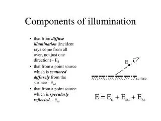
Local Illumination • Local shading
BRDF • Ratio of light coming from one directionthat gets reflected in another direction • Bidirectional Reflectance Distribution Function Incoming direction Outgoing direction
BRDF • Bidirectional Reflectance Distribution Function • 4D • 2 angles for each direction • R(θi ,i ;θo, o)
Slice at constant incidence • 2D spherical function highlight incoming incoming Example: Plot of “PVC” BRDF at 55° incidence
Unit issues - radiometry • We will not be too formal in this lecture • Typical issues: • Directional quantities vs. integrated over all directions • Differential terms: per solid angle, per area, per time • Power, intensity, flux
Light sources • Today, we only consider point light sources • For multiple light sources, use linearity • We can add the solutions for two light sources • I(a+b)=I(a)+I(b) • We simply multiply the solution when we scale the light intensity • I(s a) = s I(a) a b
Light intensity • 1/r2 falloff • Why? • Same power in all concentric circles
Incoming radiance Surface • The amount of light received by a surface depends on incoming angle • Bigger at normal incidence • Similar to Winter/Summer difference • By how much? • Cos law • Dot product with normal • This term is sometimes included in the BRDF, sometimes not n
Ideal Diffuse Reflectance Surface • Assume surface reflects equally in all directions. • An ideal diffuse surface is, at the microscopic level, a very rough surface. • Example: chalk, clay, some paints
Ideal Diffuse Reflectance • Ideal diffuse reflectors reflect light according to Lambert's cosine law.
Ideal Diffuse Reflectance Surface • Single Point Light Source • kd: diffuse coefficient. • n: Surface normal. • l: Light direction. • Li: Light intensity • r: Distance to source n r l
Ideal Diffuse Reflectance – More Details • If n and l are facing away from each other, n • l becomes negative. • Using max( (n • l),0 ) makes sure that the result is zero. • From now on, we mean max() when we write •. • Do not forget to normalize your vectors for the dot product!
Ideal Specular Reflectance Surface • Reflection is only at mirror angle. • View dependent • Microscopic surface elements are usually oriented in the same direction as the surface itself. • Examples: mirrors, highly polished metals. n r l
Non-ideal Reflectors • Real materials tend to deviate significantly from ideal mirror reflectors. • Highlight is blurry • They are not ideal diffuse surfaces either …
Non-ideal Reflectors • Simple Empirical Model: • We expect most of the reflected light to travel in the direction of the ideal ray. • However, because of microscopic surface variations we might expect some of the light to be reflected just slightly offset from the ideal reflected ray. • As we move farther and farther, in the angular sense, from the reflected ray we expect to see less light reflected.
The Phong Model Surface • How much light is reflected? • Depends on the angle between the ideal reflection direction and the viewer direction . n r l Camera v
The Phong Model Surface • Parameters • ks: specular reflection coefficient • q : specular reflection exponent n r l Camera v
The Phong Model • Effect of the q coefficient
How to get the mirror direction? Surface n r l r