DINO Communication System
180 likes | 362 Vues
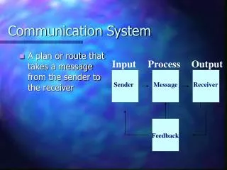
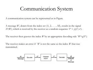
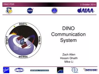
DINO Communication System. Zach Allen Hosam Ghaith Mike Li. Purpose. Establish two-way communication link between satellite and ground station. Link must allow transfer of map files from satellite to ground. Must allow transmission of health and status data from satellite to ground.

DINO Communication System
E N D
Presentation Transcript
DINO Communication System Zach Allen Hosam Ghaith Mike Li
Purpose • Establish two-way communication link between satellite and ground station. • Link must allow transfer of map files from satellite to ground. • Must allow transmission of health and status data from satellite to ground. • Must allow the satellite radios and flight computer to receive command lines transmitted by ground station. Colorado Space Grant Consortium
Requirements Imposed by other Subsystems • Data Rate: must be high enough to accommodate all data • 20 kbytes per topographical map • 255 bytes per Health and Status Packet • 5 kbytes per uploaded schedule • Antenna • Non-deployable patch (preferable): constrained to 25.6 cm by 25.6 cm space. • Deployable monopole: must be shorter than 47.5 cm. Colorado Space Grant Consortium
Requirements Imposed by COMM on other Subsystems • Power: • Receiver: 5 V at 90 mA (450 mW) • Transmitter • Active mode: 12 V at 1.4 A (16.8 W) • Idle mode: 12 V at 90 mA (450 mW) • External TNC (tentative): 12 V at 400 mA (4.8 W) • Data: • Map files should not exceed approx. 25 kB in size. Colorado Space Grant Consortium
Requirements Imposed by COMM on other Subsystems • Structures • Mass • Two Transceivers • 170 grams each • 2 x 170 grams = 340 grams total • External TNC • 40 g • Antenna • Patch << 1kg • Monopole: 23 g • Dimensions • Two Transceivers • 4.9 x 2.3 x 1.2 inches each • External TNC • 6.1 x 7.3 x 1.3 inch • Antenna • Patch 9.8 x 3.9 x 0.07 inch • Monopole: 18 inches long • 17 inch x 1/8 inch • 1 inch middle section that is 1/2 inch wide Colorado Space Grant Consortium
Subsystem Block Diagram • All Data lines use RS-232 Serial • Transmitter operates at 12 V when active, 5 V idle. • Receiver operates at 5 V. • External TNC: 12 V line, allows 9,600 bps link to ground. • Internal TNC proven to be reliable at 1,200 bps. Antenna 12 V line voltage (5 V when idle) 1.4 A 16.8 W transmitting (450 mW idle) 5 V line voltage 90 mA 450 mW (constant) Transmitter Kenwood TH-D7 Receiver Kenwood TH-D7 RS-232 Serial 9,600 bps (during setup only) RS-232 Serial 9,600 bps (during setup only) Internal TNC Internal TNC Legend External Terminal Node Controller (TNC) Power Line Data Line 12 V line voltage 400 mA, 4.8 W (constant) RS-232 Serial 9,600 bps (constant) Colorado Space Grant Consortium
Design • Transceivers • Two Kenwood TH-D7 radios: dual band 70cm / 2m, with internal TNC’s. • Reasons • Allows two distinct channels for uplink and downlink, respectively. • Built-in TNC. • Heritage from 3CS mission. • 70 cm downlink, 2m uplink. • TNC – Two options: • External TNC: Timewave PK-96 • Advantage: performs well at 9,600 baud. • Disadvantages: • Requires modifying the Kenwoods’ filters to achieve 9,600 baud. • Requires additional mass, volume, and power. • Internal TNC • Advantage: proven to perform reliably at 1,200 baud on previous missions. • Disadvantage: Greatly reduces data rate. Colorado Space Grant Consortium
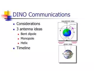
Design (continued) • Antenna • Patch • Pros • Preferable gain pattern • Non-deployable • Cons • Could occupy a lot of space on nadir surface • Complicated design process • Expensive • Monopole • Pros • Simple design • Does not take up space on the satellite’s surface • Cons • Deployable Colorado Space Grant Consortium
Illustration of Patch Design ~25 cm Metal Patch ~10 cm 436 MHz coax feed Dielectric Substrate r = 37 ± 1 145 MHz coax feed Mount on Nadir Plate Colorado Space Grant Consortium
Illustration of Monopole Design Dual Band Monopole Deploy from Nadir Plate Colorado Space Grant Consortium
Analysis: Power Requirements • Daytime Operation • Receiver: 0.45 W (5 V, 90 mA) always. • TNC: 4.8 W (12 V, 400 mA) always. • Transmitter: 16.8 W (12 V, 1.4 A) for approx. 2 minutes, otherwise same as Receiver (0.45 W). • Nighttime Operation • Receiver: 0.45 W (5 V, 90 mA) always. • TNC: 4.8 W (12 V, 400 mA) always. • Transmitter: 16.8 W (12 V, 1.4 A) for approx. 4 seconds, otherwise same as Receiver (0.45 W). • Safe Mode • Same as nighttime. Colorado Space Grant Consortium
Analysis: Calculating Transmission Time • We need to find the transmission time in order to find the exact power requirements over the course of one day. • Time needed to send one packet: • 10 bits/byte * 256 bytes/packet 1200 bits/sec = 2.133 sec/packet • Total transmission time (assuming 25 kB per pass during daytime): • 2.133 sec/packet * 25 kB/pass 256 bytes/packet = 208.3 sec/pass = ~ 3.5 minutes (absolute minimum) • May be approx. twice the minimum (resending, errors, etc.) • This is a realizable amount of time. Colorado Space Grant Consortium
Analysis: Link Budget Link Budget Form courtesy of Dr. Stephen Horan, New Mexico State University. Colorado Space Grant Consortium
Link Budget (cont.) • Margins for different slant angles • 5 deg: 6.4 dB • 12.5 deg: 9.1 dB • 15 deg: 10.1 dB Diagram Reference: Vincent L. Pisacane and Robert C. Moore, Eds., Fundamentals of Space Systems. New York: Oxford University Press, 1994. Colorado Space Grant Consortium
Test Plan • Set up ground station in flight configuration • Setup spacecraft in flight configuration (deploy antennas if necessary) • Transfer files to and from spacecraft CDH system • Measure throughput • Adjust link as necessary Colorado Space Grant Consortium
Parts List and Estimated Costs • Transceivers • Two Kenwood TH-D7 radios: one for uplink, the other for downlink. • Uplink: 2 m band (~145 MHz), Downlink: 70 cm band (~436 MHz). • Cost: $359.95 each. • External TNC (tentative) • Timewave PK-96 • Cost: $219.95 Colorado Space Grant Consortium
Parts List (continued) • Patch antenna parts • Dielectric Substrate as big as 10 x 10 inches • Need at least two: one for testing, other for flight • Cost: anywhere between $20 and $200 • Metal Patch • Coaxial Feed • Monopole Antenna • Cost: $30 (Estimated) Colorado Space Grant Consortium
Issues and Concerns • Patch Antenna Issues • Design process still in early stages: no absolute guarantee that the patch will work within the allocated space. • High dielectric substrate may prove costly (+$200). • May not be able to achieve correct polarization: 3 dB loss in power. • Monopole Antenna Issues • Impedance matching complicated for dual band tuning – may need two antennas. • Baud Rate Issues • Must learn how to connect external TNC to radios to achieve 9600 bps baud rate. • Internal TNC’s not known to perform well at other than 1200 bps (which may be too slow), but proven reliable at 1200 bps. Colorado Space Grant Consortium