Download
1 / 14
2.06k likes | 7k Vues
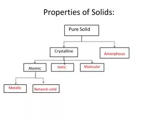
Chapter 7. Mechanical Properties of Solids. 1. Initial. 2. Small load. 3. Unload. bonds. planes. stretch. still. & planes. sheared. shear. Some mechanical testing… Tension test Hardness test Compression test Impact test Flexural test Fatigue test

E N D
Chapter 7 Mechanical Properties of Solids
1. Initial 2. Small load 3. Unload bonds planes stretch still & planes sheared shear Some mechanical testing… Tension test Hardness test Compression test Impact test Flexural test Fatigue test Shear/Torsion test Creep test d plastic d elastic + plastic F will cover in Chapter 9: Failure of Materials F 3. Unload linear linear elastic elastic d return to initial F d = deformation/elongation/deflection plastic d Non-linear elastic d • Why study mechanical properties? • as a mechanical engineer… • how to measure mechanical properties & • what these properties represent. • -- may be used to design structures @ • components using predetermined • materials such that unacceptable levels • of deformation or failure will not occur. • as a structural engineer… • how to determine stresses & stresses • distributions within members that are • subjected to loads. • -- analyze & predict various stresses using • experimental & structural analysis. • as a materials & metallurgical engineer… • concerned with producing & fabricating • materials to meet service requirements as • predicted by these stress analysis. • -- understand relationship between • microstructure of the materials & their • mechanical properties. Mechanical properties of materials… - reflect the relationship between its response or deformation to an applied load. -- its behavior when subjected to external load(shows elastic & plastic deformation before failure). - measure using various mechanical testing. 1. Initial Concept of elastic deformation Common mechanical properties… Hardness Ductility Yield strength Toughness Brittleness Tensile strength Modulus of Malleability Fracture strength elasticity Flexural strength materials return to its original dimension after tensile force is removed. Mechanical Properties of Solids Elastic means reversible! Concept of plastic deformation materials are deformed to such an extent such that it cannot return to its original dimension. Linear- elastic 2. Small load bonds stretch Elastic deformation Plastic deformation d elastic F
Mechanical Properties of Solids F F t F Ao s d /2 F s - d d L e = e = F L TS L w L o F w o o y o specimen extensometer Neck – acts as stress concentrator d /2 Typical response of a metal L strain gauge F F t s length t = A o q F t x y 90º - q Ao 90º F t mechanical testing experiment data experiment result mechanical properties Tension test [Universal Testing Machine (UTM)] Load, F Elongation, Surface area, Ao Poisson’s ratio, v Engineering stress, Engineering strain, True stress, T True strain, T Modulus of elasticity, E Yield strength, Tensile strength TS Fracture strength F Ductility (%EL @ %RA) Toughness (area under graph) Consider: Linear elastic deformation Typical tension test Typical stress-strain curves for hypothetical materials Adapted from Fig. 7.2, Callister & Rethwisch 3e. Concept of engineering stress Concept of engineering strain 1. Tensile strain: 1. Tensile stress, s: 2. Shear stress, t: F t s = A o 2. Lateral strain: original area Stress has units: N/m2 or lbf /in2 before loading 3. Shear strain: g = Dx/y= tan q
Mechanical Properties of Solids eL Graphite Ceramics Semicond e Metals Alloys Composites /fibers Polymers L n = - e 1200 e s 10 00 Diamond 8 00 6 00 E = Si carbide 4 00 Tungsten Carbon fibers only Al oxide Molybdenum Si nitride -n Steel, Ni C FRE(|| fibers)* 2 00 E Tantalum <111> Si crystal Platinum A ramid fibers only Cu alloys <100> 10 0 E (GPa) Zinc, Ti 8 0 Silver, Gold A FRE(|| fibers)* Glass - soda Aluminum 6 0 Glass fibers only Based on data in Table B.2, Callister & Rethwisch 3e. Composite data based on reinforced epoxy with 60 vol% of aligned carbon (CFRE), aramid (AFRE), or glass (GFRE) fibers. Magnesium, G FRE(|| fibers)* 4 0 Tin e Concrete GFRE* 2 0 Linear- CFRE * G FRE( fibers)* G raphite 10 8 elastic C FRE( fibers) * 6 AFRE( fibers) * Polyester 4 PET PS Epoxy only PC 2 PP HDP E 1 0.8 0.6 Wood( grain) PTF E 0.4 LDPE 0.2 mechanical testing experiment data experiment result mechanical properties Tension test [Universal Testing Machine (UTM)] Load, F Elongation, Surface area, Ao Poisson’s ratio, v Engineering stress, Engineering strain, True stress, T True strain, T Modulus of elasticity, E Yield strength, Tensile strength TS Fracture strength F Ductility (%EL @ %RA) Toughness (area under graph) Elastic deformation region 1. Modulus of Elasticity, E (also known as Young's modulus) E values for selected materials Units: E: [GPa] or [psi] n: dimensionless 2. Poisson's ratio,n metals: n ~ 0.33ceramics: n ~ 0.25polymers: n ~ 0.40
Mechanical Properties of Solids TS Elastic+Plastic F = fracture or ultimate strength Neck – acts as stress concentrator at larger stress y when ep = 0.002 = 0.2% offset stress engineering Typical response of a metal strain engineering strain mechanical testing experiment data experiment result mechanical properties Tension test [Universal Testing Machine (UTM)] Load, F Elongation, Surface area, Ao Poisson’s ratio, v Engineering stress, Engineering strain, True stress, T True strain, T Modulus of elasticity, E Yield strength, Tensile strength TS Fracture strength F Ductility (%EL @ %RA) Toughness (area under graph) Plastic deformation region 1. Yield strength, Stress at which noticeableplastic deformation has occurred. sy Elastic initially engineering stress, s engineering stress, s permanent (plastic) after load is removed e engineering strain, ep engineering strain, e e = 0.002 p Adapted from Fig. 7.10 (a), Callister & Rethwisch 3e. plastic strain 2. Tensile Strength, TS Maximum stress on engineering stress-strain curve. Metals: occurs when noticeable necking starts. Polymers: occurs when polymer backbonechains are aligned & about to break.
Mechanical Properties of Solids Graphite/ Graphite/ Metals/ Composites/ Ceramics/ Polymers Metals/ Alloys fibers Ceramics/ Semicond Alloys 5000 Semicond C fibers Aramid fib 3000 E-glass fib 2000 qt Steel (4140) A FRE (|| fiber) 1000 Diamond W (pure) GFRE (|| fiber) a Ti Composites/ (5Al-2.5Sn) C FRE (|| fiber) a Steel Polymers (4140) cw Si nitride fibers Cu (71500) hr Cu (71500) Al oxide 2000 Steel (1020) 300 ag Al (6061) qt a Steel Ti (pure) (4140) 200 Ta (pure) (MPa) a Al 1000 (6061) Si crystal wood(|| fiber) 100 a <100> Nylon 6,6 Ti (5Al-2.5Sn) W (pure) 700 Glass-soda PET PC PVC GFRE ( fiber) 600 40 cw Concrete Cu PP (71500) C FRE ( fiber) 500 30 Mo (pure) strength, TS A FRE( fiber) a (MPa) Steel 400 H DPE (4140) cd Graphite Steel (1020) 20 300 L DPE , y ag s Al (6061) hr 10 Steel 200 (1020) ¨ a Ti (pure) Tensile Ta (pure) hr Cu in ceramic matrix and epoxy matrix composites, since in tension, fracture usually occurs before yield. (71500) Hard to measure, Yield strength, since in tension, fracture usually occurs before yield. Hard to measure 100 wood ( fiber) dry 70 PC 60 Nylon 6,6 a Al 1 (6061) 50 PET humid PVC 40 PP 30 H DPE 20 LDPE Tin (pure) 10 mechanical testing experiment data experiment result mechanical properties Tension test [Universal Testing Machine (UTM)] Load, F Elongation, Surface area, Ao Poisson’s ratio, v Engineering stress, Engineering strain, True stress, T True strain, T Modulus of elasticity, E Yield strength, Tensile strength TS Fracture strength F Ductility (%EL @ %RA) Toughness (area under graph) Plastic deformation region & TS values for selected materials (room temperature)
Mechanical Properties of Solids smaller %EL E ngineering tensile stress, s larger %EL Adapted from Fig. 7.13, Callister & Rethwisch 3e. Engineering tensile strain, e mechanical testing experiment data experiment result mechanical properties Tension test [Universal Testing Machine (UTM)] Load, F Elongation, Surface area, Ao Poisson’s ratio, v Engineering stress, Engineering strain, True stress, T True strain, T Modulus of elasticity, E Yield strength, Tensile strength TS Fracture strength F Ductility (%EL @ %RA) Toughness (area under graph) Plastic deformation region 3. Ductility 4. Toughness Energy to break a unit volume of material. Approximate by the area under the stress-strain curve. Plastic tensile strain at failure. -- shows a significant plastic deformation before rupture. Engineering - small toughness (ceramics) L L tensile f o = x 100 % EL stress, s large toughness (metals) L o Ao Lo Lf Af - A A f o = % RA x 100 very small toughness A o (unreinforced polymers) Engineering tensile strain, e Brittle fracture: elastic energyDuctile fracture: elastic + plastic energy
Stress-Strain curves for typical polymers brittle polymer plastic elastomer elastic moduli – less than for metals Mechanical Properties of Solids mechanical testing experiment data experiment result mechanical properties Tension test [Universal Testing Machine (UTM)] Load, F Elongation, Surface area, Ao Poisson’s ratio, v Engineering stress, Engineering strain, True stress, T True strain, T Modulus of elasticity, E Yield strength, Tensile strength TS Fracture strength F Ductility (%EL @ %RA) Toughness (area under graph) True Stress & Strain Note: Surface area, A changes when sample stretched. True stress True strain Adapted from Fig. 7.22, Callister & Rethwisch 3e. Fracture strengths of polymers ~ 10% of those for metals. Deformation strains for polymers > 1000% –for most metals, deformation strains < 10%. Adapted from Fig. 7.16, Callister & Rethwisch 3e.
Mechanical Properties of Solids Flexural test… - most common test for ceramics. - ceramic materials are more brittle than metals. Why is this so? - consider mechanism of deformation -- in crystalline, by dislocation motion. -- in highly ionic solids, dislocation motion is difficult. * few slip systems. * resistance to motion of ions of like charge (e.g., anions) past one another. F cross section L/2 L/2 d R b d = midpoint rect. circ. deflection Flexural strength: s Material (MPa) E(GPa) fs F Si nitride Si carbide Al oxide glass (soda-lime) 250-1000 100-820 275-700 69 304 345 393 69 (rect. cross section) x F slope = d (circ. cross section) d linear-elastic behavior mechanical testing experiment data experiment result mechanical properties Flexural test [Universal Testing Machine (UTM)] Load, F Elongation, (deflection) Modulus of elasticity, E Flexural strength, fs Flexural test… - materials with room T behavior is usually elastic but with brittle failure. -- show little plastic deformation before failure. - 3-Point Bend Testing often used. -- tensile tests are difficult for brittle materials. Typical 3 point bend test Adapted from Fig. 7.18, Callister & Rethwisch 3e. Determine elastic modulus according to: Typical values: (rect. cross section) (circ. cross section) Data from Table 7.2, Callister & Rethwisch 3e.
Mechanical Properties of Solids Press the indenter that is harder than the metal Into metal surface. Withdraw the indenter apply known force measure size e.g., of indent after 10 mm sphere removing load Measure hardness by measuring depth or width of indentation. Smaller indents d D mean larger hardness. most brasses easy to machine cutting nitrided plastics Al alloys steels file hard tools steels diamond increasing hardness mechanical testing experiment data experiment result mechanical properties Hardness test [hardness machine] Hardness number (HN) Covert to , TS, E Hardness… - Resistance to permanently indenting the surface. - Large hardness means: -- resistance to plastic deformation or cracking in compression. -- better wear properties. Type of hardness test Brinell hardness test Rockwell hardness test Vickers microhardness test Knoop microhardness test General procedure… Typical rockwell hardness tester
Detail of hardness testing techniques & measurement Table 7.5 Mechanical Properties of Solids mechanical testing experiment data experiment result mechanical properties Hardness test [hardness machine] Hardness number (HN) Covert to , TS, E
Design or Safety Factors d 1045 plain carbon steel: L o s = 310 MPa y 5 TS = 565 MPa F = 220,000N • Design uncertainties mean we do not push the limit. • Factor of safety, N Often N is between 1.2 and 4 • Example: Calculate a diameter, d, to ensure that yield does not occur in the 1045 carbon steel rod below. Use a factor of safety of 5. d = 0.067 m = 6.7 cm
Summary • Stress and strain: These are size-independent measures of load and displacement, respectively. • Elastic behavior: This reversible behavior often shows a linear relation between stress and strain. To minimize deformation, select a material with a large elastic modulus (E or G). • Plastic behavior: This permanent deformation behavior occurs when the tensile (or compressive) uniaxial stress reaches sy. • Toughness: The energy needed to break a unit volume of material. • Ductility: The plastic strain at failure.