Introduction to Directional Drilling
1.33k likes | 2.78k Vues
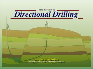
Introduction to Directional Drilling. Wayne Longstreet Drilling Manager - Dragon Oil (Turkmenistan) Ltd. Objective of Directional Drilling.

Introduction to Directional Drilling
E N D
Presentation Transcript
Introduction to Directional Drilling Wayne Longstreet Drilling Manager - Dragon Oil (Turkmenistan) Ltd
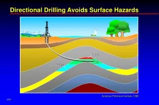
Objective of Directional Drilling Controlled directional drilling is the science of deviating a wellbore along a planned course to a subsurface target whose location is a given lateral distance and direction from the vertical.
Historical Background • Originally only as a remedial operation. • Now primarily a reservoir optimization tool. • First well surveying in 1920’s in Oklahoma. Acid Bottle Inclinometer. • 1929 a directional inclinometer with magnetic needle first used. Acid bottle technique proved to have error margin of @10 degrees (low).
Historical Background (cont’d) • As more accurate survey tools developed, it was found most boreholes were “crooked”. • Thus the emerging science of geology as given a boost when it was realized that the measured depth of producing zones was in many cases different from the vertical depth.
Historical background (cont’d) • 1930’s saw the first controlled directional well drilled in Huntington Beach, California. 1933 used to drill under Sunnyside Cemetery in Long Beach. • 1934 first relief well drilled in Conroe, Texas.
Historical background (cont’d) • Today the technology incorporates: Horizontal, EM-MWD, SAG-D, Multi-Laterals, Extended Reach Drilling, Downhole Adjustable Gauge Stabilizers, Downhole Adjustable Motors, Bicentric Bits, 3D Wells, Underbalanced Wells, River Crossings, CTU Drilling.
Reasons for Drilling Directional Wells
Geological Considerations • Knowledge of the local geology is essential to the directional driller.
Where Under the Earth Are We?
Surveying • Regardless of the type of survey instrument (single-shot, multishot, steering tool, SRO Gyro, MWD, EM-MWD) three pieces of information are known. • Survey Measured Depth. • Borehole Inclination. • Borehole Azimuth (corrected for true north).
Directional Surveying Permits • The determination of the bottomhole location relative to the surface location or another reference system. • The location of excessive doglegs or hole curvature. • The monitoring of inclination and azimuth during drilling. • The orientation of deflection tools.
Survey Calculation Methods • Average Angle • Radius of Curvature. • Minimum Radius of Curvature.
Average Angle • Calculates the average of the angles at the top and bottom of the course section and assumes this to be the inclination and direction of the wellbore. • Oldest and least accurate method. • Easiest to calculate by hand. • Accurate when BUR is small and survey stations are close together.
Radius of Curvature • Each course length is defined by points at the top and bottom, and the wellbore is assumed to be curved in either or both the vertical and horizontal projections. • More complex calculations than average angle. • Accurate when stations are far apart with higher rates of curvature.
Minimum Radius of Curvature • Projects the actual dogleg and accounts for the severity of the dogleg on the drillstring. • Most accurate method of calculation in use today. • The use of computers and programmable calculators have made this the only real tool used today.
Radius of Uncertainty • All tools have a range of accuracy. • The assumption is made that errors will average out, but this still leaves us with a cone of potential error. • Critical in thin sections and extended horizontal wells. • Use of LWD, Geosteering, and geology help the directional driller.
The Earth’s Magnetic Field • Theory #1: Rotation of the earth’s mantle in relation to the liquid core is thought to produce electrical currents. • Theory #2: The internal circulation currents (similar to phenomenon observed at the periphery of the sun) of the liquid iron in the earth’s core acts as the source according to the principle of a self-excited dynamo.
Magnetic Declination • The angle between magnetic north and geographic north (true north) is defined as the angle of declination. • All surveys are converted to true north. • Angles of declination to the west of true north can be written as negative numbers, to the east as positive numbers.
Magnetic North True North Angle of Declination Visual
Magnetic Interference • Caused by: • Drill String. • Fish left in hole. • Nearby casing. • Geology (Iron Pyrite, Hematite) • Magnetic “hot spot” in Drill Collar. • Fluctuations in the earth’s magnetic field. (minor)
Minimizing Drill String Interference • Eliminate magnetism by using “non-mag” collars (monel). • The connection area can be magnetized due to mechanical torque. (azimuth errors in 10’s of degrees) Never space within 2’ of connection. • Do not space in the center. Collars are bored from both ends leaving a ridge in center and potential magnetic hot spot.
Drill String Interference (cont’d) • Non-mag stabilizers are magnetic near the blades (hard facing can be very magnetic). • Amount of non-mag BHA is affected by: • Latitude. • Hole Inclination. • Distance from North/South hole azimuth. • Location (Alaska has used as much as 165 ft above magnetometer).
Vertical Section and Closure • VS is the length of the horizontal displacement defined by it’s azimuth in relation to the target. • Closure is the length of the horizontal displacement passing through the survey point.
Azimuth • Wellbore direction measured in the horizontal plane and expressed in degrees from the North direction starting at 0 and continuing clockwise to 360.
Dog Leg Severity • AKA BUR. • Expressed in degrees per unit of length.
Defining Objectives • Careful planning is essential for success. • Each well will have specific objectives defined by the reservoir or business units. • The design must be tailored to meet all of the objectives.
Location • DD involves drilling a hole from one point in space (surface location) to another point in space (target). • Local coordinate system must be known so the target can be accurately correlated to the target. • Most directional plans will use wellhead location as 0.
Target Size • During drilling the trajectory is constantly monitored in relation to the target. • Costly decisions are constantly being made to ensure that the well objectives are met. • Today’s technology allows us to drill extremely accurate wells. • Cost of the well is largely dependent upon accuracy required.
Cost vs Accuracy • Operators often adopt arbitrary target sizes or tolerances which do not reflect the geological realities of the reservoir. • Many needless correction runs have been made. • Hard Boundaries must be clearly defined. Legal limits, fault lines, pinch outs. • Communication and Team Work required.
Wellbore Profile • Given surface location, target location, target tvd, and rectangular coordinates, it is possible to determine the geometric well profile from surface to bottomhole target. • General directional well types: • Straight, Build and Hold, “S” Wells, Slant Wells, Horizontal, and Multi-Lateral.
Determining KOP • Kick Off Point is the depth at which the well will be deviated off the vertical. • Selection of KOP is made by considering the geometrical wellpath and geological characteristics. • Optimum inclination is determined by maximum permissible BUR and location of the target.
Determining Build & Drop Rates • Maximum permissible build/drop rate is determined by: • Total depth of well, and hole size. • Torque & Drag limitations. High DLS results in higher T&D except in horizontal wells. • Geology - high bur’s not always possible in soft formations. • Limitations of tools, casing, drill strings.
Types of Directional Wells • Build and Hold • “S” Wells • Slant Wells • Horizontal Wells • Multi-Laterals
Anti-Collision • As platform and pad drilling becomes more popular anti-collision planning is critical. • Radius of uncertainty. • Lead angle for rotary drilling. • Accurate well plan map essential.
Steering Tools • Continuous readout when drilling without rotation. Some available now that will allow slow rotation - unreliable. • Jointed pipe operations require a “wet connect” system. • Wet connects are unreliable and time consuming. • System of choice for coil drilling.
Magnetic Single & Multi Shots • Camera or Electronic (digital). • Very Accurate. • Still the basic surveying tool. • Multi-shot surveys used to legally confirm open hole wells drilled with MWD. Pump down - time out.