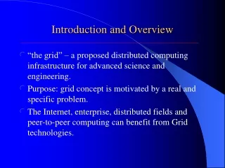
Introduction and Overview
520 likes | 740 Vues
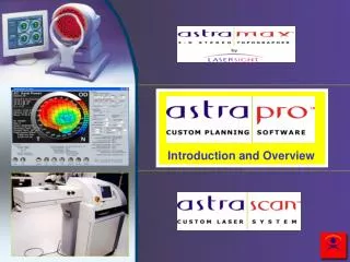
Introduction and Overview. General Operational Flow. AstraMax. Diagnostic exams (AstraMax, refraction, rigid contact lens fitting, wavefront). AstraPro. Surgery planning. LaserScan LSX AstraScan and AstraScan XL Configurations. Data is input from AstraMax which includes:

Introduction and Overview
E N D
Presentation Transcript
General Operational Flow AstraMax Diagnostic exams (AstraMax, refraction, rigid contact lens fitting, wavefront) AstraPro Surgery planning LaserScan LSX AstraScan and AstraScanXL Configurations
Data is input from AstraMax which includes: Shape, pupil sizes, registration data, pachymetry, asphericity(Q), and other proprietary data points Refractive data is input New shape is calculated to maintain the eye’s natural prolate asphericity while correcting the refractive error to the best fit elipsoid model New shape is calculated with respect to the scotopic pupil AstraPro: Custom Ablation Planning Software
The volume of the ablation is described by the intersection of the existing, detected anterior surface of the cornea and the ideal cornea surface targeting the pre-operative asphericity The intersection between the measured surface and the ideal surface must be as large as the scotopic pupil seen projected at the anterior surface of the cornea AstraPro Principals: Volume Description
SHAPE The shape of the cornea must be measured using triangulation methods to derive elevation with very high resolution (<3 microns)(AstraMax) Highly irregular corneas with significant discontinuities of the cornea shape will require stereo or multi-view devices that can provide accurate data for these type of cases (AstraMax) More common irregularities may be measured using more common topographers Required Data
The Shape of a Sphere Increase in effective power • Sphere = single radiusof curvature • Snell’s Law calculates an increase in power towards the peripherydue to a change in angle of incidence • The characteristic of a spherical surface with gradually increasing effective power toward the periphery is called spherical aberration
Spherical Aberration Increase in effective power • As the pupil becomes larger at night, the larger the effect of viewing through the higher effective power of the peripheral cornea • If the cornea has spherical aberrations, this results in night myopia and decreased contrast sensitivity Photopic(day pupil) Scotopic(night pupil)
Higher Power = more + Asphere: Prolate Less increase in effective power • Not spherical • A “normal” cornea is about 3 D flatter peripherally than centrally • This is the Prolate shape Photopic(day pupil) Scotopic(night pupil)
Asphere: Prolate • A normal corneais prolate and has an average “Q” value of –0.26 • Negative means that the shape flattens from the center to the periphery Scotopic(night pupil) Photopic(day pupil)
Asphere: Oblate • Aspherehas noasphericity:Q = 0 • Asphere surfaces that steepen toward the periphery have + asphericity (Q>0) and are termed Oblate • Myopic refractive surgical treatments increase + asphericity, i.e., moves shape towards Oblate • Exaggerates the effects of spherical aberration, i.e., more night vision problems
Prolate Vs. Oblate (Asphericity) Oblate (Q > 0) Prolate (Q < 0)
SHAPE SCOTOPIC PUPIL The projection of the scotopic pupil on the anterior surface of the cornea is measured in dark conditions with an infrared instrument (AstraMax) Shaping the ablation profile to provide full coverage of the scotopic pupil will minimize aberrations under dimly lit conditions Required Data
SHAPE SCOTOPIC PUPIL MANIFEST REFRACTION The subjective refraction is the most important parameter for the determination of the ideal aconic surface for the cornea Required Data
AstraMax Data Anterior Cornea Posterior Cornea Spatial Resolved Refractive Error Corneal Thickness and Anterior Chamber Depth Scotopic Pupil Size
The vectorial sum of the refractive properties of the anterior corneal surface and the subjective refraction = the new surface The new targeted surface will be optimized to respect the cornea’s pre-operative asphericity, i.e., to preserve the natural prolate nature of the cornea Calculating the Ideal Aconic Surface
AstraPro: Summary of Features • Imports Corneal Topography • Optimized Treatment Planning • Advanced Surgical Planning • Safety Features
Imports Corneal Topography • Reduces the roughness of the eye • Allows treatment of irregular corneas • Allows treatment of asymmetric corneas
Circular Treatments • Circular, tissue-saving ablation profiles • Profile centered in pupil • Optimizes optical zone for astigmatic treatments
Optimized Treatment Planning • Circular Treatments • Pupil Center Offset • Blend Zone • Ablation Modulation Function (AMF)
Circular Vs. Elliptical Treatments Pupil Elliptical zone along the minor axis of the astigmatism (too much ablation outside the pupil) Elliptical zone along the major axis of the astigmatism (does not cover optical zone of pupil)
Pupil Center Offset • Pupil center offset from the visual axis • Final surface is offset from the pupil center • Saves tissue by not having to increase the optical zone to compensate for the offset
Pupil Center Offset Pupil Pupil Center Area inside pupil not treated when OZ = Pupil Visual Axis
Pupil Center Offset Pupil Center Pupil Additional treatment causes a much deeper ablation when OZ > Pupil Visual Axis
Pupil Center Offset Visual Axis Pupil Center Initial Surface Final Surface Optical Zone
Blend Zone • Blend between optical and treatment zones • Gaussian function ensures continuous curve along the target eye surface • Profile is blended to the target eye, not to a flat surface
Ablation Modulation Function • Maintains or improve prolate shape • Corrects for laser fluence reduction in periphery • This algorithm may be extensible to the laser platform directly
Energy Fluence = Area Laser Fluence Reduction B1 B2 The area of B2 is larger than the area of B1, so B2 has less fluence if the energy remains constant.
Advanced Surgical Planning • Aspheric Ellipsoid Model • Contact Lens Over-Refraction Method • Target Refraction • Optical and Treatment Zones • Nomogram Adjustment • Target Z-Axis Offset • Effective Refractive Change
Aspheric Ellipsoid Model • Initial and final eye surfaces • Parameters: K1, K2, axis, asphericity (Q), defined as the apical keratometry • Corrects for the keratometric index of refraction • Novel algorithm to add spherical refraction to aspherical surfaces
Contact Lens Over-Refraction • CLOR method for irregular or asymmetric surfaces • Set of rigid contact lenses • May provide best correction
Target Refraction • Allows surgeon to record target refraction separately from spectacle or contact lens refraction • Ideal for mono-vision patients
Optical and Treatment Zones • The default OZ is set to the scotopic pupil diameter or 6mm, whichever is larger • The TZ is set to 1mm (SER myopia) or 2.5mm (SER hyperopia) larger than the optical zone. • The surgeon may modify the OZ and TZ within the range 3-9mm
Nomogram Adjustment • Persistent Sphere/Cylinder adjustments separately for myopic astigmatism, hyperopic astigmatism, and mixed astigmatism • Sphere/Cylinder adjustment may be modified for individual treatments • Applied to refraction, prior to AMF
Target Z-Axis Offset • Provides an offset to the Target Z-Axis • Automatically computed by the software • Optimizes treatment plan (saves tissue) for irregular surfaces
Effective Refractive Change • Estimated from the corneal topography and apical keratometry • Computed in terms the surgeon can understand, using the spherical approximation of the initial and final surfaces
Safety Features • Treatment depth computed normal to the eye surface and compared with pachymetry at all points • Warning messages and restrictions • Patient data (name, gender, eye) provided for visual confirmation • Advanced Visual Display
Visual Display • Keratometric axial power map duplicates image from topographer, as a double-check • Preop elevation difference map from best fit asphere of keratometry • Predicted postop elevation difference map from best fit asphere of keratometry • Ablation profile (depth map)
AstraPro: Planning Screen Topography data is displayed Patient Data is automatically imported form AstraLink
AstraPro: Planning Screen Surgical parameters entered Resultant treatment dimensions
The calculations to optimize the new corneal shape targets the natural pre-operative asphericity Potentially results in: Decreased spherical aberrations Improved night vision Improved contrast sensitivity Summary