Download
1 / 17
170 likes | 345 Vues
Figure 8.1 Track Layout with Input Sensors and Output Switches and Output Tracks. D. A. =. 0. 1. :. S. u. p. p. l. y. A. F. o. r. w. a. r. d. T. 1. =. 0. :. T. r. a. c. k. 1. s. e. t. t. o. S. u. p. p. l. y. A. S. w. i. t. c. h. 3. T. r. a. c.

E N D
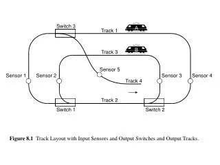
Figure 8.1 Track Layout with Input Sensors and Output Switches and Output Tracks.
D A = 0 1 : S u p p l y A F o r w a r d T 1 = 0 : T r a c k 1 s e t t o S u p p l y A S w i t c h 3 T r a c k 1 T r a c k 3 S e n s o r 5 S e n s o r 1 S e n s o r 2 S e n s o r 3 S e n s o r 4 T r a c k 4 T r a c k 2 S w i t c h 1 S w i t c h 2 Figure 8.3 Track Power is connected to one of Two Power Sources: A and B.
Figure 8.4 Track Direction if all Switches are Asserted (SW1 = SW2 = SW3 = 1)
Figure 8.8 Working diagrams of train positions for each state.
Figure 8.9 Tcontrol.vwf vector waveform file for simulation.
Figure 8.10 Simulation of Tcontrol.vhd using Tcontrol.vec vector file.