Download
1 / 22
220 likes | 339 Vues
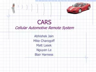
CARS Cellular Automotive Remote System. Abhishek Jain Mike Charogoff Matt Lasek Nguyen Le Blair Harness. Objective. Effectively work in a group to produce a working prototype of a cellular automotive remote system.

E N D
CARSCellular Automotive Remote System Abhishek Jain Mike Charogoff Matt Lasek Nguyen Le Blair Harness
Objective • Effectively work in a group to produce a working prototype of a cellular automotive remote system. • At expo the demonstration system will send and receive information via a cellular phone.
Functionality • Resembles OnStar • More universal, many more and different convenience features. • Through CARS the user can control: • Starter • Security system • Heat and cooling system
Functionality • CARS obtains and sends information about: • Temperature • Theft • Vehicle location • Accidents
Optional Features • User obtains information via voice messages • Control movement of vehicle (prototype) • Gives information of vehicle distance from user • Information received from car on a terminal • PC or microcontroller
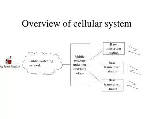
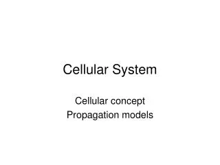
C.A.R.S.- System Overview “Home” Vehicle Speaker, Microphone, and Solenoids Cellular Phone Home or Cellular Phone Speaker, Microphone, and Solenoids Wireless Audio Amp Audio Amp Solenoid Driver, DAC and Audio Amp Solenoid Driver, DAC and Audio Amp Alternate implementation does Not require solenoids, DAC, Or Speaker on Home system. Misc. Digital Outputs Heater, Door L/U, …etc. MCU (W/ ADC on-board) MCU (W/ ADC on-board) Memory (RAM or Serial EEPROM) Misc.Analog Inputs (Temp., Accelerometer) Memory (RAM or Serial EEPROM) Misc. Digital Inputs (Bumper, Optical Encoders, Door Switch, ..etc. GPS LCD or Serial link to PC
Preliminary Board Layout(And Mechanical Design of OPTIONAL Mobile Platform)
Tone Reception and Decoding Cellular Phone Speaker, Microphone, and Solenoids • Principle of Operation • Audible tones generated by the phone are converted • to an electrical signal by the microphone (transducer). • This electrical signal is amplified and fed to an ADC. • The digitized signal is decoded. The specific decoding method has yet to be established, but one possible method would involve calculating the number of samples between zero crossings (or peak values). This number (n) would be unique for tones of different frequencies if the sample rate is adequate (> ~ 30k/sec). • After decoding, the Microcontroller executes the issued command (i.e. start vehicle, Lock doors, Unlock doors, …etc.). (2) (LM380?) Audio Amp (1) Solenoid Driver, DAC and Audio Amp MCU PIC? 68HC1X? (W/ ADC on-board) (4) (3)
Tone Creation and Transmission Cellular Phone Speaker, Microphone, and Solenoids • Principle of Operation: (Very much the opposite of tone reception process) • The phone number of the “Home” station is stored in the cell phone so that the auto-dial function may be used. Two Solenoids are positioned (variable to accommodate various models) to push the appropriate buttons (thus calling the base). • The Vehicle-based system then waits for the Home station to transmit an initialization tone to be sure that it has “picked-up”. (Alternatively, Vehicle-based system waits for ringing to stop followed by a delay. This simplifies Home system, but may sacrifice reliability and features). • Now the Vehicle-based system may transmit by converting its stored data into an analog signal (via a DAC). • This analog signal is amplified (LM380/LM386?) and converted into sound by way of a small speaker (transducer). • Design Considerations: • Frequency response of Microphone and speaker. • Solenoid voltage/power requirement (12V?). • How standard is auto-dial on current generation cell phones? • (Audio) “cross-talk” between speaker and microphone. • How to hang-up? Another solenoid? • How much data may be stored on memory device of choice? Audio Amp (2) (1) Solenoid Driver, DAC and Audio Amp (4) (3) MCU PIC? 68HC1X? (W/ ADC on-board) Stored Data EEPROM? SRAM? FLASH?
Solenoid Control MCU (1) Principle of Operation: A digital signal is used to control the driver circuit. Driver circuit consists of discrete components or an IC. Current spikes and other large, inductive load concerns must be analyzed. Solenoid only needs to be energized for a fraction of a second in order to push the appropriate button. Overall power use should be relatively small. (2) Solenoid Driver (L294/295 ?) (3) Solenoid Cell Phone
Digital Inputs To Rest of Block Diagram • GPS: • Take existing GPS device to track route of car. • Data consisting of longitude, latitude, and possibly distance or speed of car sent via a serial data link to the microprocessor. • Door Indictor: • Notifies home if user forgets to lock car door. • Implemented by a push-button switch, which will be pushed if the door is locked and released if it is unlocked. • Bumper Switch (Optional): • Use spring-loaded switch so that when demonstration car hits an object the switch will be pushed. This will cause the car to change directions and avoid being stuck in one spot. • Optical Encoder (Optional): • Device will measure certain aspects of demonstration car such operating speed, direction and will relay this information, in the form of digital pulses, to the microprocessor. • Microprocessor will then use this data to control the car’s motion. MCU (W/ ADC on-board) GPS Optical Encoder (Optional) Door Indicator Bumper Switch (Optional)
Analog Inputs To Rest of Block Diagram • Temperature Sensor: • A thermocouple or RTD (resistance temperature detector) will be used to obtain a temperature reading inside and/or outside car. The measurement data will be sent to the user when the user gives the appropriate command. • Anti-Theft Device: • A vibration sensor, possibly piezoelectric, will be used to detect any disturbances to the car. If a disturbance is detected, the data will be sent to the microprocessor which will alert the user. • Accident Alarm: • Consists of a combination of devices that notifies emergency personal if the car is in an accident and gives them information about the location and severity of the accident. This will be done by using GPS (previously mentioned), accelerometer, and voice recordings. The accelerometer will give information about the magnitude of the accident and from this data will determine the severity of the crash. MCU Temperature Anti-Theft Device Accident Alarm
Digital Outputs To Rest of Block Diagram • Heater/Air Conditioner: • Device will allow the user to warm/cool the interior of the vehicle from home by use of cell phone • Heater will be implemented by use of a lamp which will be activated by a switch (MOSFET, BJT). • Air conditioner can be realized by using a fan which would also be initiated by a switch. • LED’s: • The realization of the peripherals such as activating the door lock/unlock, starter, headlamps, and horns used as the vehicle locater will be demonstrated using an array of LED’s. • Motor Control (Optional): • This device allows control of the demonstration car’s motion. It does this by sending data to the car’s motor and wheels to control the car’s speed and direction. • Auto-Dial Control: • This device consists of a solenoid which pushes buttons on the cell phone so that it can transit data. MCU Motor Control (Optional) Auto-Dial Control Door Unlock/Lock Lights Heater Air Conditioner
Division of Labor • Abhishek Jain-Digital Outputs • Matt Lasek/Nguyen Le-Inputs (excluding audio features) • Mike Charogoff –Audio Input/Output • Blair Harness-Programming, Micro-controller
Risks and Contingency Plans Areas of risk: • Microprocessor • Learning hardware/software use of micro controller • Shouldn’t be an issue, several group members are familiar with technology • Button pusher • Ability to push (and possibly hold for speed dial) buttons • Number of buttons we will need to push • Plan on using solenoids for pushing buttons • Multiple fixed solenoids vs single solenoid on servo drive • Audio quality needed for tone recognition • Shouldn’t be a problem • Add filters/amplification if needed
Risks and Contingency Plans Areas of risk: • Voice reply (optional) • Strings of digits sent back – requires ‘base station’ module • If possible, add voice reply • Time vs quality considerations • Number of messages needed • Storage requirements • Accident alert thresholds • Should not report accident under hi-performance vehicle acceleration • Will need thresholds • Might have to setup differently for different cars
Summary • CARS convenience features include: • Remote start/idle system • Heat/Cool the interior of your car • Lock/Unlock your car doors • Anti-Theft System • Accident Alarm System • Temperature Sensor • GPS