Download
1 / 71
720 likes | 892 Vues
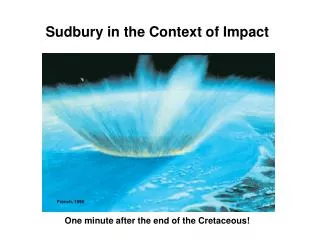
Sudbury in the Context of Impact. French, 1998. One minute after the end of the Cretaceous!.

E N D
Sudbury in the Context of Impact French, 1998 One minute after the end of the Cretaceous!
How Common are Impact Craters on Earth? We all know how abundant they are on the Moon where erosion and tectonic activity have not been able to erode them. On Earth there are about 200 reliably identified impacts but only a few are really large. After Dence, 1991
What Happens During an Impact? First let’s look at a relatively small crater and the various stages of its development
1. During the Contact/Compression Stage the projectile penetrates to a depth approximating its diameter and initiates a supersonic shock wave that propagates through the target rocks. Projectile Shock Wave French, 1998
2. During the Compression Stage, the shock wave expands further followed by a rarefaction or pressure release wave. material is physically moved downward and outward away from expanding crater Ejecta Rarefaction or Release Wave Shock Wave material flows away from expanding crater French, 1998
3. During the Excavation Stage, material is removed from the crater as an ejecta curtain and also as vapour. A small melt sheet may form as a lining on the cavity wall depending on the size of the crater. material continues to be displaced downward and outward from the crater walls. Vapour Plume Ejecta Curtain Melt Sheet French, 1998
4. At the end of the Excavation Phase, the so-called transient cavity has reached its maximum size Transient Cavity French, 1998
5. The Modification Stage represents the final phase of crater development. Almost instantly, the transient cavity starts to be filled in by centripetal slumping of material from the upper part of the crater. The ejecta curtain collapses to form an ejecta blanket on neighbouring surfaces and major fracture zones develop adjacent to the original crater wall. Ejecta Centripetal Slumping Crater Fill Zone of strongly fractured rock French, 1998
Here is another image of a small crater French, 1998
And here is an image of a small, simple bowl-shaped crater on the moon. NASA Website
What Happens during a larger impact? Essentially it’s the same sequence of stages that we have examined for small craters with one major exception.
This summarizes what happens Impact Site Ejecta Ejecta Melt Vapourized Ejected Ejected Displaced
2. Excavation Stage (I’ve omitted Stage 1) Ejecta Rarefaction/release wave Melt material Flow Shock Wave French, 1998
3. End of Excavation Stage. Here’s the difference! In sufficiently large impacts, the material in the center of the transient cavity starts to rebound in what’s termed the Modification Stage. Ejecta material Flow. Initiation of Central Uplift French, 1998
4. And here’s the final structure after the completion of the Modification Stage. There is a well-developed central uplift within a relatively wide flat crater which has been modified by zones of marginal collapse/slumping. There is also a well-developed melt sheet. If the impact is really large, the ejecta layer can be traced all around the globe (e.g. The K-T boundary layer from the Chixelub Impact). Marginal Slump Blocks Ejecta Layer Melt Layer Central Uplift French, 1998
Another view of one half of a larger complex crater with a central uplift and a melt sheet Crater Rim Central Uplift Centripetal Faults Fracture Zone beneath crater floor French, 1998
Here’s a view of lunar crater Tycho, with a well-developed central uplift. You can see the slumping that is taking place around the circumference of the crater. NASA Website
Another lunar crater being modified by exceptionally well-developed slump features. These may be slumping into the crater along listric normal faults. Possibly analogous to “super-faults” as proposed by Spray and others NASA Website
Even larger impacts form what are termed peak-ring craters where the central uplift forms a well-defined ring. This is a view of the Shrodinger crater on the moon. Crater Rim Outer Melt Sheet Peak-Ring Structure Inner Melt Sheet NASA Website
Sudbury in the Context of a Peak Ring Crater Outer Melt Ring now Eroded Except for Offset Dykes Central Melt Sheet (Preserved SIC) Peak Ring Ames and Farrow
Indicators of Impact • Microscopic Indicators (Shock Metamorphism) • Kink Banding • Planar Deformation Features (PDF’s) • Destruction of Crystal Structure and Formation of Diaplectic (Thetomorphic) Glasses • Formation of High Pressure Mineral Phases (Quartz Polymorphs, Diamond etc) • Vesiculation and Formation of Melt • Megascopic indicators (Field Geology) • Shape • Shatter Cones • Breccia • Ejecta Blankets • Melt Sheets
What is Shock Metamorphism and why is it different from normal metamorphic processes? • Shock metamorphism refers to the various structural and phase changes that occur in minerals during the passage of a hyper-velocity shock wave. • It is characterized by ultra-high pressures and temperatures imposed during an extremely short period of time (fractions of a second?). • This differs from normal metamorphism where the effects are active over a period of years (thermal effects adjacent to small igneous intrusions) to millions of years (orogenies). • The effects of shock metamorphism are thus due to non-equilibrium processes and this is reflected by the often erratic distribution of these effects.
P-T Variables ComparingNormal Metamorphism vs Shock Metamorphism Field of “Normal” Metamorphic P-T Conditions French, 1998
Stages of Shock Metamorphism Possible Field of “Normal” Metamorphism Low (Megascopic) Shock Effects PDF’s Start to Form High Pressure Phases Melting, Vesiculation etc French, 1998
Comparison of P-T conditions, strain rates and reaction times for various processes under regional (left) and shock (right) metamorphism
Here are some photomicrographs illustrating some of the more common petrographic indicators of shock metamorphism
Kink-Banding in Biotite French, 1998
Development of new mineral phases along pre-existing cleavages. In this case the development of an iron oxide phase in hornblende.
Development of multiple sets of planar deformation features (PDF’s), often best developed in quartz but also common in other minerals such as plagioclase.
PDF’S in slightly annealed rocks are commonly found as linear arrays of fluid inclusions (these are known as decorated PDF’s). With increasing degree of annealing the PDF’s become progressively more diffuse (right hand picture) and will eventually disappear. This has happened on the South Range of Sudbury.
Increasing intensity of shock metamorphism can lead to destruction of the crystal structure of minerals. In this example plagioclase (colourless phase in the left diagram has been converted to isotropic maskelynite (black phase in the right diagram) without disturbing the igneous texture of the rock.
Eventually, the target rocks are subject to wholesale melting and vesiculation
Lithic breccias form annular rings adjacent to and under large impacts. They are most commonly formed in the floor of the crater and thus their distribution gives a general idea of the original size of the structureThis example is from the Vredefort Structure in South Africa.
Lithic breccias like this consist of randomly oriented clasts of local country rock set in a very fine-grained matrix. The matrix can be either a v.f.g. igneous-textured rock, glass or, very commonly, fine-grained rock flour or cataclasite. This example is from Sudbury.
This map shows the general distribution of Sudbury Breccia around the Sudbury Basin. Although this map suggests that breccia mostly occurs within 10 km of the SIC, occurrences of Sudbury Breccia have been reported more than 100 km from the SIC – this suggests that the Sudbury Structure represents a very large impact indeed with a diameter in excess of 200 km. Sudbury Breccia Shatter Cones Anomalous Ir Ames et al, 2005
Shatter cones are a more or less ubiquitous phenomenon at well-documented impact sites and their presence has become an expected criterion to their identification. The identification of shatter cones at Sudbury by Robert Dietz in 1964 was the first real indication of an impact origin for the Sudbury Structure. French, 1998
This is a photograph of the original discovery site of shatter cones at Sudbury.
This slide shows the distribution and orientation of shatter cones around the Sudbury Basin. In undeformed impacts, cones point in and upwards towards the point of impact and, if post-impact deformation at Sudbury is removed, this is generally true here also. Naldrett (after Bray)
Perhaps the most obscure megascopic indicator of an impact is the discovery of distal ejecta horizons. Here is an example of the probable ejecta from Sudbury which has recently been found in Michigan, Minnesota, Western Ontario and possibly in Greenland. The ejecta here is about 1 m thick. Addison et al, 2005
This diagram shows the locations where the ejecta has been found as far as 850 km west of the Sudbury Structure. Bear in mind that the ejecta from the K-T impact at Chixelub has been found all around the world, even if it is only a few mm thick in places. Distal Ejecta Sites Impact Site After Addison et al, 2005
Here is the stratigraphic column showing the location of the ejecta layer at the contact between the Gunflint and Rove Formations of the Penokean Supergroup. Note the ages of the two dated tuff horizons at 1875 and 1836 Ma which bracket the age of the Sudbury impact at 1850 Ma. After Addison et al, 2005 Dated Tuff Layers @ 1875 Ma & 1836 Ma
Although the ejecta sheet has not yet been radiometrically dated, its age is determined as lying between that of tuff horizons found above and below the ejecta. Here is a zircon concordia plot showing an age of ~1827 Ma for a tuff lying above the ejecta. Addison et al, 2005
What’s the definitive proof that you’re actually looking at an impact ejecta sheet? You look for evidence of shock metamorphism such as this well-developed set of PDF’s found in Minnesota. Addison et al, 2005
Paleo-setting of the Sudbury Structure(The Red Units weren’t there at the time!) At the time of Impact (1850Ma), the Superior Province was surrounded by passive and active marginal belts. OOPS! What Happened Here?
Tectonic-Structural-MetallogenicHistory of the Sudbury District Hydrothermal Wanapitei Impacts 37 Ma Sedimentation Intrusions Tectonics Magmatic Mineralization Grenville Orogeny is Much Later and has Nothing to do with Sudbury Structure Sudbury 1851 Ma Penokean - Mazatzal Orogenies Blezardian Orogeny Rifting and Start of Huronian Deposition After Ames and Farrow