Download
1 / 26
810 likes | 2.23k Vues
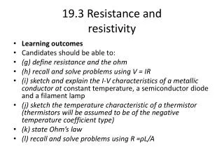
19.3 Resistance and resistivity. Learning outcomes Candidates should be able to: ( g) define resistance and the ohm (h) recall and solve problems using V = IR

E N D
19.3 Resistance andresistivity • Learningoutcomes • Candidates should be able to: • (g) define resistance and the ohm • (h) recall and solve problems using V = IR • (i) sketch and explain the I-V characteristics of a metallic conductor at constant temperature, a semiconductor diode and a filament lamp • (j) sketch the temperature characteristic of a thermistor (thermistorswill be assumed to be of the negative temperature coefficient type) • (k) stateOhm’slaw • (l) recall and solve problems using R =ρL/A
19.3 Resistance andresistivity (g) define resistance and the ohm. (h) recall and solve problems using V = IR.
19.3 Resistance andresistivity TheRESISTANCE of a conductor isthe ratio of thepotentialdifferenceappliedacrossit, tothecurrentpassingthroughit. Or in symbols:
19.3 Resistance andresistivity Resistanceismeasured in ohms (W). 1 W = 1 V A-1 Sincethetermsignificantresistancerefersto a smallresistance, itiscommonfor a resistor tohave kilo ohm (K W ) and mega ohm (M W ) values. 1 k W = 1 kilo ohm = 10 3W 1 MW = 1 mega ohm = 10 6W 1 G W = 1 giga ohm = 10 9W
19.3 Resistance andresistivity • Thegreatertheresistance of a component, the more difficultitisforchargetoflowthroughit. • Whenthe free electronscollidewiththe positive ions in thelattice, theygive up some of theirenergytothem. Thiscollisionsgenerateheatthat causes thetemperature of the metal toincrease. • Wesaythat a current produces a heatingeffect.
19.3 Resistance andresistivity 1. The label on a small heater specifies its electric performance as 115 V, 4.50 A. a. What is the resistance of the heating filament in this heater? b. How much current will it draw when connected to the following: (i) 120 V, (ii) 220 V (iii)60.0 V 2. Three resistors are available for testing a 9.00 V battery. Resistor A has has 5.00 kΩ of resistance, resistor B has 5.00 Ω of resistance, and resistor C has 0.0500Ω of resistance. a. How much current will each resistor draw? b. Which resistor is more useful for testing if the battery is dead? Explain. 3. An electrical device of 37.2 Ω resistance performs best when the current is 3.62 A. How much voltage should be applied? 4. An electronic device performs best with a 1.20 V battery , when the current is between 3.50 mA and 4.20 mA. What is the range of possible resistances forthiselectronicdevice?
19.3 Resistance andresistivity (i) sketch and explain the I-V characteristics of a metallic conductor at constant temperature, a semiconductor diode and a filament lamp.
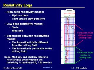
19.3 Resistance andresistivity Voltage-Current Graph for a Metal Conductor • When metals are heated it causes the atoms in the metal to vibrate more. Imagine an electron in a current travelling through heated copper. • It's trying to flow through the metal but the atoms are vibrating more, so they are going to get in the way more, causing more collisions. More collisions gives more resistance.
19.3 Resistance andresistivity • Voltage-Current Graph for a Metal Conductor
19.3 Resistance andresistivity • Voltage-Current Graph for a filament lamp.
19.3 Resistance andresistivity • Voltage-Current Graph for a semiconductor diode.
19.3 Resistance andresistivity (j) sketch the temperature characteristic of a thermistor.
19.3 Resistance andresistivity • Resistance-temperature Graph of a thermistor.
19.3 Resistance andresistivity (k) stateOhm’slaw
19.3 Resistance andresistivity • TheOhm´slawstatethat: “ Ifthetemperature of a conductor keptconstant, it´sresistanceisconstantover a widerange of appliedpotentialdifferences. Thereforepotential differenceisdirectlyproportionaltothecurrent throughthe conductor”.
19.3 Resistance andresistivity TostudyOhm´slawweusually use thefollowingcircuit:
19.3 Resistance andresistivity Ohm's law Ohm's law states that: The ratio of the current in a conductor to the potential difference (voltage difference) between its ends is a constant as long as the temperature stays constant. This constant is called the RESISTANCE of the conductor. Resistance = Voltage (V)/Current(I) or R = V/IVoltage = Current x Resistance or V = IRResistance is measured in units called Ohms ( W ). The resistance of a piece of wire is 1 ohm if a current of 1 A flows through it when a voltage of 1 V is applied between its ends.
19.3 Resistance andresistivity • Using an ammeter and a voltmeter to measure resistance. To measure the resistance of say a piece of wire or a resistor we must find the voltage (potential difference) between its two ends and the current flowing through it. An ammeter is always connected in series with the component and a voltmeter is always connected in parallel with the component.
19.3 Resistance andresistivity (l) recall and solve problems using
19.3 Resistance andresistivity Resistivity • The resistance of a material depends on: (a) the temperature(b) the dimensions of the specimen(c) the material from which the specimen is madeThe property of the material that affects its resistance is called the resistivity of the material and is given the symbol r.The resistivity of a material is the resistance between two opposite faces of a 1 m3 specimen of the material. Resistivity (r) = R A/ L The units for resistivity are Wm.Example resistivities: Copper 1.69x10⁻⁸Wm Non-metals 104Wm
19.3 Resistance andresistivity Question 1: What length of an alloy wire of resistivity 5.0 x 10⁻⁷W m and diameter 0.50 mm is required to make a standard 6.0 W resistor?
19. Current of electricity • Solution: Theresistanceisgivenbytheequation: R = rx L /A L= RxA /r ( when: A = pd2/4) L = (6.0) x (p [0.50 x10⁻³] 2 /4) / 5.0 x 10⁻⁷ Then: L = 2.4 m
19. Current of electricity Question 2: The table in the next slide is a selection of some of the specifications to be found in a manufacturer´s catalogue of wires for use in electrical circuits. Carry out calculations necessary to complete the table.