Download
1 / 13
130 likes | 337 Vues
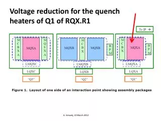
Voltage reduction for the quench heaters of Q1 of RQX.R1. A. Verweij, 22 March 2012. Protection with heaters, without parallel resistance and without energy extraction. A. Verweij, 22 March 2012. A. Verweij, 22 March 2012. A. Verweij, 22 March 2012. Tests performed on 26/8/2009

E N D
Voltage reduction for the quench heaters of Q1 of RQX.R1 A. Verweij, 22 March 2012
Protection with heaters, without parallel resistance and without energy extraction. A. Verweij, 22 March 2012
Tests performed on 26/8/2009 1200 V on heaters of Q1, Q2a, Q2b, and Q3 Heater circuit YT1121 of Q1 shows breakdown at 1200 and 1100 V (OK at 1000V). The decision was taken to use only heater YT1111 of Q1 (with standard 2x450 V, 7 mF, tau=136 ms, Q=2.86 kJ). A. Verweij, 22 March 2012
Theoretical resistance of one strip of a heater: R=50e-8*6.517/2/(15e-3*25e-6)=4.34 W 4 heaters, each with 2 strips, so in total 8x4.34=34.7 W So each heater circuit: 17.4 W Tests performed on 26/8/2009: R1=R2=18.6 W (including leads) A. Verweij, 22 March 2012
A. Verweij, 23 Feb 2012 A. Verweij, 22 March 2012
MIITs summary(from K. Sasaki, T. Nakamoto, A. Yamamoto KEK) x 0.95 See p10 x 0.9*2 +0.92*3 *1: expected from Case 1 and quench detection time delay in Table below (see also p10 to p12) *2: MIITs would be reduced by (6800/7150)^2 = 0.9 *3: MIITs would be increased by 0.92 due to the time-to-quench delay of 20 ms A. Verweij, 23 Feb 2012
Check of ThotvsMIIt’s value (case 4) I = 6800 A B = 8.6 T MIIt’s = 13.3 (teff = 0.618 s) • Worst case: • No cooling • No helium • Peak field • No long heat transfer A. Verweij, 22 March 2012
FWT & FWD become conducting We have no measurement of the currents in the magnets, only the currents in the converters, and the voltage over the current leads. DCCT’s in the FWT and FWD can be added (takes 1 day). Tests were done in the past. Otherwise we rely on PSpice simulation to get the MIIt’s. A. Verweij, 22 March 2012
Conclusion • KEK has calculated that reduction of 2x450 V to 2x400 V with the same C increases the quench on-set at 7 kA by 20 ms (and increases the MIIt’s by 1 MA2s). Hot spot temperatures would stay below 300 K for I=6800 A, for inner and outer cable in the high, medium, and low field areas of the magnet. KEK does not guarantee full protection for intermediate currents due to a lack of experimental data. • The increase of C from 7 to 9 mF would probably reduce the quench on-set (and hence the hot spot temperature) only slightly for high currents (where the quench onset after heater firing is short w.r.t. the heater current time constant). At low currents, the 30% increase of heater energy might be more substantial. • The 2nd (redundant) heater (YT1121) will be connected to the QPH with target of 2x400 V, 9 mF. See talk Reiner. The QPS_OK will be set at 95% of U_HDS_NOM (so 95%x800=760 V). • RQX has now been commissioned to 4 TeV equivalent. • During HWC in beginning 2012 only one heater discharge test at 0 A has been done. • During HWC before LS1 one or more quenches will be performed, if possible with 2 additional DCCT’s on the FWD and FWT. These quenches will qualify the protection of the triplet circuits, and give valuable input for the PSpice model. The program for these quenches will be defined later. • ELQA HV tests on heater circuit YT1121 should from now on be performed at 1.2*800=960 V. A. Verweij, 22 March 2012