Mu2e Production Target Remote Handling
10 likes | 93 Vues
Mu2e Production Target Remote Handling. By: Michael R. Campbell, Fermi National Accelerator Laboratory, 630-840-6495, mikecam@fnal.gov. System Layout. Production Solenoid Endcap. Target.

Mu2e Production Target Remote Handling
E N D
Presentation Transcript
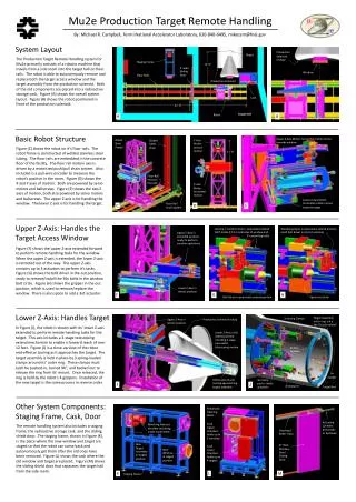
Mu2e Production Target Remote Handling By: Michael R. Campbell, Fermi National Accelerator Laboratory, 630-840-6495, mikecam@fnal.gov System Layout Production Solenoid Endcap Target The Production Target Remote Handling system for Mu2e primarily consists of a robotic machine that travels from a side room into the target hall on floor rails. The robot is able to autonomously remove and replace both the target access window and the target assembly from the production solenoid. Both of the old components are placed into a radioactive storage cask. Figure (A) shows the overall system layout. Figure (B) shows the robot positioned in front of the production solenoid. Staging Frame 12’-6” 5’ wide Sliding Door Window Floor Rails Production Solenoid Cask 42’-8” Target Hall Robot A B Basic Robot Structure Upper Z-Axis Motor: horizontal motion in/out towards window Robot Base Frame Y-AxisMotor: vertical motion Guided Cable Chain Figure (C) shows the robot on it’s floor rails. The robot frame is constructed of welded stainless steel tubing. The floor rails are embedded in the concrete floor of the facility. The floor rail motion axis is driven by a motorized push/pull chain system. Also included is a pull-wire encoder to measure the robot’s position in the room. Figure (D) shows the X and Y axes of motion. Both are powered by servo motors and ballscrews. Figure (E) shows the two Z axes of motion, both also powered by servo motors and ballscrews. The upper Z axis is for handling the window. The lower Z axis is for handling the target. 11’-8” Floor Rail Position Encoder X-Axis Motor: horizontal motion Lower Z-Axis Motor: horizontal motion in/out towards target Floor Rail Drive System C D E Upper Z-Axis: Handles the Target Access Window Camera / machine vision + pneumatic extend LVDT locate X,Y,Z coordinates of window and it’s mounting bolts Window gripper in pneumatic extend position (with bolt driver in retract position) Upper Z-Axis inextended position, ready to perform window operations Figure (F) shows the upper Z-axis extended forward to perform remote handling tasks for the window. When the upper Z-axis is extended, the lower Z-axis is retracted out of the way. The upper Z-axis contains up to 3 actuators to perform it’s tasks. Figure (G) shows the bolt driver in the out position, ready to remove/install the 36x bolts in the window bolt circle. Figure (H) shows the gripper in the out position, which is used to remove/replace the window. There is also space to add a 3rd actuator. Lower Z-Axis in retract position F G H Spare tool plate Bolt driver in pneumatic extend position Lower Z-Axis: Handles Target Target Assembly outer ring, a.k.a. the “bicycle wheel” 3x Spring Clamps Upper Z-Axis in retract position Production SolenoidEndcap In Figure (I), the robot is shown with its’ lower Z-axis extended to perform remote handling tasks for the target. This axis includes a 3-stage telescoping extend mechanism to enable a forward reach of over 12 feet. Figure (J) is a close-up view of the robot end-effector tooling as it approaches the target. The target assembly is held in place by 3 spring-loaded clamps around its’ outer ring. These clamps must each be pushed-in, turned 90°, and backed out to release the ring from its’ mount. Once released, the ring is held by the robot’s 4 grippers. Installation of the new target is the same process in reverse order. Lower Z-Axis in full extend position, including 3-stage pneumatic telescoping motion 4x Grip Handles 6x Spokes Robot end-of-arm tooling approaching target assembly 3x Clamp push / rotate actuators I J 4x Grippers Target Rod Other System Components: Staging Frame, Cask, Door Pneumatic Opening Doors Actuating Cylinder: pneumatic or hydraulic Cask Upper Chamber: holds up to 5 windows Matching features simulate mounting inside experiment The remote handling system also includes a staging frame, the radioactive storage cask, and the sliding shield door. The staging frame, shown in Figure (K), is the place where the new window and target are staged so that the robot can come back and autonomously get them after the old ones have been removed. Figure (L) shows the cask where the old window and target are placed. Figure (M) shows the sliding shield door that separates the target hall from the side room. Overhead Roller Track New Target Assembly in staged position 8” thick Stainless SteelSliding Door Cask Lower Chamber: holds up to 4 targets New Window in staged position K L M Staging Frame