Download
1 / 73
730 likes | 849 Vues
This unit provides a comprehensive overview of key concepts in computer architecture, focusing on instruction sets, pipeline execution, and cache mechanisms. It discusses Cycles Per Instruction (CPI), performance metrics, different ISA implementations (like MIPS), and design guidelines for efficient processing. The unit covers hazards in pipelining, the role of datapaths and controllers, and visual representations of the pipelining process. This material is adapted from UCB slides and serves as a quick reference for understanding fundamental architecture principles.

E N D
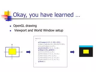
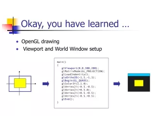
Advanced Computer Architecture Unit 02: Overview of Instruction Sets, Pipelines, and Caches
Quick overview of everything you should have learned Adapted from UCB slides
Cycles Per Instruction (Throughput) “Average Cycles per Instruction” • CPI = (CPU Time * Clock Rate) / Instruction Count • = Cycles / Instruction Count “Instruction Frequency” Adapted from UCB slides
Example: Calculating CPI bottom up Run benchmark and collect workload characterization (simulate, machine counters, or sampling) Base Machine (Reg / Reg) Op Freq Cycles CPI(i) (% Time) ALU 50% 1 .5 (33%) Load 20% 2 .4 (27%) Store 10% 2 .2 (13%) Branch 20% 2 .4 (27%) 1.5 Typical Mix of instruction types in program Design guideline: Make the common case fast MIPS 1% rule: only consider adding an instruction of it is shown to add 1% performance improvement on reasonable benchmarks. Adapted from UCB slides
performance(x) = 1 execution_time(x) n = Performance(X) = Execution_time(Y) Performance(Y) Execution_time(X) Definition: Performance • Performance is in units of things per sec • bigger is better • If we are primarily concerned with response time • X is n times faster than Y means: Adapted from UCB slides
A "Typical" RISC ISA • 32-bit fixed format instruction (3 formats) • 32 32-bit GPR (R0 contains zero, DP take pair) • 3-address, reg-reg arithmetic instruction • Single address mode for load/store: base + displacement • no indirection • Simple branch conditions • Delayed branch see: SPARC, MIPS, HP PA-Risc, DEC Alpha, IBM PowerPC, CDC 6600, CDC 7600, Cray-1, Cray-2, Cray-3 Adapted from UCB slides
Example: MIPS ( MIPS) Register-Register 6 5 11 10 31 26 25 21 20 16 15 0 Op Rs1 Rs2 Rd Opx Register-Immediate 31 26 25 21 20 16 15 0 immediate Op Rs1 Rd Branch 31 26 25 21 20 16 15 0 immediate Op Rs1 Rs2/Opx Jump / Call 31 26 25 0 target Op Adapted from UCB slides
signals Datapath vs Control Datapath Controller • Datapath: Storage, FU, interconnect sufficient to perform the desired functions • Inputs are Control Points • Outputs are signals • Controller: State machine to orchestrate operation on the data path • Based on desired function and signals Control Points Adapted from UCB slides
Adder 4 Address Inst ALU 5 Steps of MIPS DatapathFigure A.2, Page A-8 Instruction Fetch Instr. Decode Reg. Fetch Execute Addr. Calc Memory Access Write Back Next PC MUX Next SEQ PC Zero? RS1 Reg File MUX RS2 Memory Data Memory L M D RD MUX MUX Sign Extend IR <= mem[PC]; PC <= PC + 4 Imm WB Data Reg[IRrd] <= Reg[IRrs] opIRop Reg[IRrt] Adapted from UCB slides
MEM/WB ID/EX EX/MEM IF/ID Adder 4 Address ALU 5 Steps of MIPS DatapathFigure A.3, Page A-9 Instruction Fetch Execute Addr. Calc Memory Access Instr. Decode Reg. Fetch Write Back Next PC MUX Next SEQ PC Next SEQ PC Zero? RS1 Reg File MUX Memory RS2 Data Memory MUX MUX IR <= mem[PC]; PC <= PC + 4 Sign Extend WB Data Imm A <= Reg[IRrs]; B <= Reg[IRrt] RD RD RD rslt <= A opIRop B WB <= rslt • Data stationary control • local decode for each instruction phase / pipeline stage Reg[IRrd] <= WB Adapted from UCB slides
Reg Reg Reg Reg Reg Reg Reg Reg Ifetch Ifetch Ifetch Ifetch DMem DMem DMem DMem ALU ALU ALU ALU Cycle 1 Cycle 2 Cycle 3 Cycle 4 Cycle 5 Cycle 6 Cycle 7 Visualizing PipeliningFigure A.2, Page A-8 Time (clock cycles) I n s t r. O r d e r Adapted from UCB slides
Pipelining is not quite that easy! • Limits to pipelining: Hazards prevent next instruction from executing during its designated clock cycle • Structural hazards: HW cannot support this combination of instructions (single person to fold and put clothes away) • Data hazards: Instruction depends on result of prior instruction still in the pipeline (missing sock) • Control hazards: Caused by delay between the fetching of instructions and decisions about changes in control flow (branches and jumps). Adapted from UCB slides
Reg Reg Reg Reg Reg Reg Reg Reg Reg Reg Ifetch Ifetch Ifetch Ifetch DMem DMem DMem DMem ALU ALU ALU ALU ALU One Memory Port/Structural HazardsFigure A.4, Page A-14 Time (clock cycles) Cycle 1 Cycle 2 Cycle 3 Cycle 4 Cycle 5 Cycle 6 Cycle 7 I n s t r. O r d e r Load DMem Instr 1 Instr 2 Instr 3 Ifetch Instr 4 Adapted from UCB slides
Reg Reg Reg Reg Reg Reg Reg Reg Ifetch Ifetch Ifetch Ifetch DMem DMem DMem ALU ALU ALU ALU Bubble Bubble Bubble Bubble Bubble One Memory Port/Structural Hazards(Similar to Figure A.5, Page A-15) Time (clock cycles) Cycle 1 Cycle 2 Cycle 3 Cycle 4 Cycle 5 Cycle 6 Cycle 7 I n s t r. O r d e r Load DMem Instr 1 Instr 2 Stall Instr 3 How do you “bubble” the pipe? Adapted from UCB slides
Speed Up Equation for Pipelining For simple RISC pipeline, CPI = 1: Adapted from UCB slides
Example: Dual-port vs. Single-port • Machine A: Dual ported memory (“Harvard Architecture”) • Machine B: Single ported memory, but its pipelined implementation has a 1.05 times faster clock rate • Ideal CPI = 1 for both • Loads are 40% of instructions executed SpeedUpA = Pipeline Depth/(1 + 0) x (clockunpipe/clockpipe) = Pipeline Depth SpeedUpB = Pipeline Depth/(1 + 0.4 x 1) x (clockunpipe/(clockunpipe / 1.05) = (Pipeline Depth/1.4) x 1.05 = 0.75 x Pipeline Depth SpeedUpA / SpeedUpB = Pipeline Depth/(0.75 x Pipeline Depth) = 1.33 • Machine A is 1.33 times faster Adapted from UCB slides
Reg Reg Reg Reg Reg Reg Reg Reg Reg Reg ALU ALU ALU ALU ALU Ifetch Ifetch Ifetch Ifetch Ifetch DMem DMem DMem DMem DMem EX WB MEM IF ID/RF I n s t r. O r d e r add r1,r2,r3 sub r4,r1,r3 and r6,r1,r7 or r8,r1,r9 xor r10,r1,r11 Data Hazard on R1Figure A.6, Page A-17 Time (clock cycles) Adapted from UCB slides
Three Generic Data Hazards • Read After Write (RAW)InstrJ tries to read operand before InstrI writes it • Caused by a “Dependence” (in compiler nomenclature). This hazard results from an actual need for communication. I: add r1,r2,r3 J: sub r4,r1,r3 Adapted from UCB slides
I: sub r4,r1,r3 J: add r1,r2,r3 K: mul r6,r1,r7 Three Generic Data Hazards • Write After Read (WAR)InstrJ writes operand before InstrI reads it • Called an “anti-dependence” by compiler writers.This results from reuse of the name “r1”. • Can’t happen in MIPS 5 stage pipeline because: • All instructions take 5 stages, and • Reads are always in stage 2, and • Writes are always in stage 5 Adapted from UCB slides
I: sub r1,r4,r3 J: add r1,r2,r3 K: mul r6,r1,r7 Three Generic Data Hazards • Write After Write (WAW)InstrJ writes operand before InstrI writes it. • Called an “output dependence” by compiler writersThis also results from the reuse of name “r1”. • Can’t happen in MIPS 5 stage pipeline because: • All instructions take 5 stages, and • Writes are always in stage 5 • Will see WAR and WAW in more complicated pipes Adapted from UCB slides
Reg Reg Reg Reg Reg Reg Reg Reg Reg Reg ALU ALU ALU ALU ALU Ifetch Ifetch Ifetch Ifetch Ifetch DMem DMem DMem DMem DMem I n s t r. O r d e r add r1,r2,r3 sub r4,r1,r3 and r6,r1,r7 or r8,r1,r9 xor r10,r1,r11 Forwarding to Avoid Data HazardFigure A.7, Page A-19 Time (clock cycles) Adapted from UCB slides
ALU HW Change for ForwardingFigure A.23, Page A-37 ID/EX EX/MEM MEM/WR NextPC mux Registers Data Memory mux mux Immediate What circuit detects and resolves this hazard? Adapted from UCB slides
Reg Reg Reg Reg Reg Reg Reg Reg Reg Reg ALU ALU ALU ALU ALU Ifetch Ifetch Ifetch Ifetch Ifetch DMem DMem DMem DMem DMem I n s t r. O r d e r add r1,r2,r3 lw r4, 0(r1) sw r4,12(r1) or r8,r6,r9 xor r10,r9,r11 Forwarding to Avoid LW-SW Data HazardFigure A.8, Page A-20 Time (clock cycles) Adapted from UCB slides
Reg Reg Reg Reg Reg Reg Reg Reg ALU Ifetch Ifetch Ifetch Ifetch DMem DMem DMem DMem ALU ALU ALU lwr1, 0(r2) sub r4,r1,r6 and r6,r1,r7 or r8,r1,r9 Data Hazard Even with ForwardingFigure A.9, Page A-21 Time (clock cycles) I n s t r. O r d e r Adapted from UCB slides
Reg Reg Reg Ifetch Ifetch Ifetch Ifetch DMem ALU Bubble ALU ALU Reg Reg DMem DMem Bubble Reg Reg Data Hazard Even with Forwarding(Similar to Figure A.10, Page A-21) Time (clock cycles) lwr1, 0(r2) I n s t r. O r d e r sub r4,r1,r6 and r6,r1,r7 Bubble ALU DMem or r8,r1,r9 Adapted from UCB slides
Software Scheduling to Avoid Load Hazards Fast code: LW Rb,b LW Rc,c LW Re,e ADD Ra,Rb,Rc LW Rf,f SW a,Ra SUB Rd,Re,Rf SW d,Rd Try producing fast code for a = b + c; d = e – f; assuming a, b, c, d ,e, and f in memory. Slow code: LW Rb,b LW Rc,c ADD Ra,Rb,Rc SW a,Ra LW Re,e LW Rf,f SUB Rd,Re,Rf SW d,Rd Adapted from UCB slides
Reg Reg Reg Reg Reg Reg Reg Reg Reg Reg ALU ALU ALU ALU ALU Ifetch Ifetch Ifetch Ifetch Ifetch DMem DMem DMem DMem DMem 10: beq r1,r3,36 14: and r2,r3,r5 18: or r6,r1,r7 22: add r8,r1,r9 36: xor r10,r1,r11 Control Hazard on BranchesThree Stage Stall What do you do with the 3 instructions in between? How do you do it? Where is the “commit”? Adapted from UCB slides
Branch Stall Impact • If CPI = 1, 30% branch, Stall 3 cycles => new CPI = 1.9! • Two part solution: • Determine branch taken or not sooner, AND • Compute taken branch address earlier • MIPS branch tests if register = 0 or 0 • MIPS Solution: • Move Zero test to ID/RF stage • Adder to calculate new PC in ID/RF stage • 1 clock cycle penalty for branch versus 3 Adapted from UCB slides
MEM/WB ID/EX EX/MEM IF/ID Adder 4 Address ALU Pipelined MIPS DatapathFigure A.24, page A-38 Instruction Fetch Execute Addr. Calc Memory Access Instr. Decode Reg. Fetch Write Back Next SEQ PC Next PC MUX Adder Zero? RS1 Reg File Memory RS2 Data Memory MUX MUX Sign Extend WB Data Imm RD RD RD • Interplay of instruction set design and cycle time. Adapted from UCB slides
Four Branch Hazard Alternatives #1: Stall until branch direction is clear #2: Predict Branch Not Taken • Execute successor instructions in sequence • “Squash” instructions in pipeline if branch actually taken • Advantage of late pipeline state update • 47% MIPS branches not taken on average • PC+4 already calculated, so use it to get next instruction #3: Predict Branch Taken • 53% MIPS branches taken on average • But haven’t calculated branch target address in MIPS • MIPS still incurs 1 cycle branch penalty • Other machines: branch target known before outcome Adapted from UCB slides
Four Branch Hazard Alternatives #4: Delayed Branch • Define branch to take place AFTER a following instruction branch instruction sequential successor1 sequential successor2 ........ sequential successorn branch target if taken • 1 slot delay allows proper decision and branch target address in 5 stage pipeline • MIPS uses this Branch delay of length n Adapted from UCB slides
becomes becomes becomes if $2=0 then add $1,$2,$3 if $1=0 then add $1,$2,$3 sub $4,$5,$6 add $1,$2,$3 if $1=0 then sub $4,$5,$6 Scheduling Branch Delay Slots (Fig A.14) A. From before branch B. From branch target C. From fall through • A is the best choice, fills delay slot & reduces instruction count (IC) • In B, the sub instruction may need to be copied, increasing IC • In B and C, must be okay to execute sub when branch fails add $1,$2,$3 if $1=0 then add $1,$2,$3 if $2=0 then sub $4,$5,$6 delay slot delay slot add $1,$2,$3 if $1=0 then sub $4,$5,$6 delay slot Adapted from UCB slides
Delayed Branch • Compiler effectiveness for single branch delay slot: • Fills about 60% of branch delay slots • About 80% of instructions executed in branch delay slots useful in computation • About 50% (60% x 80%) of slots usefully filled • Delayed Branch downside: As processor go to deeper pipelines and multiple issue, the branch delay grows and need more than one delay slot • Delayed branching has lost popularity compared to more expensive but more flexible dynamic approaches • Growth in available transistors has made dynamic approaches relatively cheaper Adapted from UCB slides
Evaluating Branch Alternatives Assume 4% unconditional branch, 6% conditional branch- untaken, 10% conditional branch-taken Scheduling Branch CPI speedup v. speedup v. scheme penalty unpipelined stall Stall pipeline 3 1.60 3.1 1.0 Predict taken 1 1.20 4.2 1.33 Predict not taken 1 1.14 4.4 1.40 Delayed branch 0.5 1.10 4.5 1.45 Adapted from UCB slides
Problems with Pipelining • Exception: An unusual event happens to an instruction during its execution • Examples: divide by zero, undefined opcode • Interrupt: Hardware signal to switch the processor to a new instruction stream • Example: a sound card interrupts when it needs more audio output samples (an audio “click” happens if it is left waiting) • Problem: It must appear that the exception or interrupt must appear between 2 instructions (Ii and Ii+1) • The effect of all instructions up to and including Ii is totalling complete • No effect of any instruction after Ii can take place • The interrupt (exception) handler either aborts program or restarts at instruction Ii+1 Adapted from UCB slides
Precise Exceptions in Static Pipelines Key observation: architected state only change in memory and register write stages. Adapted from UCB slides
Gap grew 50% per year Since 1980, CPU has outpaced DRAM ... Performance (1/latency) • How do architects address this gap? • Put small, fast “cache” memories between CPU and DRAM. • Create a “memory hierarchy” CPU 60% per yr 2X in 1.5 yrs 1000 CPU 100 DRAM 9% per yr 2X in 10 yrs 10 DRAM 2000 1990 1980 Year
Apple ][ (1977) CPU: 1000 ns DRAM: 400 ns Steve Wozniak Steve Jobs 1977: DRAM faster than microprocessors
Processor Control Tertiary Storage (Tape) Secondary Storage (Disk) Second Level Cache (SRAM) Main Memory (DRAM) On-Chip Cache Datapath Registers 10,000,000s (10s ms) Speed (ns): 1s 10s-100s 100s 10,000,000,000s (10s sec) Size (bytes): 100s Ks-Ms Ms Gs Ts Memory Hierarchy of a Modern Computer • Take advantage of the principle of locality to: • Present as much memory as in the cheapest technology • Provide access at speed offered by the fastest technology Adapted from UCB slides
The Principle of Locality • The Principle of Locality: • Program access a relatively small portion of the address space at any instant of time. • Two Different Types of Locality: • Temporal Locality (Locality in Time): If an item is referenced, it will tend to be referenced again soon (e.g., loops, reuse) • Spatial Locality (Locality in Space): If an item is referenced, items whose addresses are close by tend to be referenced soon (e.g., straightline code, array access) • Last 15 years, HW relied on locality for speed Adapted from UCB slides
Bad locality behavior Temporal Locality Spatial Locality Programs with locality cache well ... Memory Address (one dot per access) Time Donald J. Hatfield, Jeanette Gerald: Program Restructuring for Virtual Memory. IBM Systems Journal 10(3): 168-192 (1971)
Managed by compiler Managed by OS, hardware, application Managed by hardware iMac G5 1.6 GHz Memory Hierarchy: Apple iMac G5 Goal: Illusion of large, fast, cheap memory Let programs address a memory space that scales to the disk size, at a speed that is usually as fast as register access
512K L2 L1 (32K Data) iMac’s PowerPC 970: All caches on-chip L1 (64K Instruction) Registers (1K)
Lower Level Memory Upper Level Memory To Processor Blk X From Processor Blk Y Memory Hierarchy: Terminology • Hit: data appears in some block in the upper level (example: Block X) • Hit Rate: the fraction of memory access found in the upper level • Hit Time: Time to access the upper level which consists of RAM access time + Time to determine hit/miss • Miss: data needs to be retrieve from a block in the lower level (Block Y) • Miss Rate = 1 - (Hit Rate) • Miss Penalty: Time to replace a block in the upper level + Time to deliver the block the processor • Hit Time << Miss Penalty (500 instructions on 21264!) Adapted from UCB slides
4 Questions for Memory Hierarchy • Q1: Where can a block be placed in the upper level? (Block placement) • Q2: How is a block found if it is in the upper level? (Block identification) • Q3: Which block should be replaced on a miss? (Block replacement) • Q4: What happens on a write? (Write strategy) Adapted from UCB slides
01234567 01234567 01234567 1111111111222222222233 01234567890123456789012345678901 Q1: Where can a block be placed in the upper level? • Block 12 placed in 8 block cache: • Fully associative, direct mapped, 2-way set associative • S.A. Mapping = Block Number Modulo Number Sets Direct Mapped (12 mod 8) = 4 2-Way Assoc (12 mod 4) = 0 Full Mapped Cache Memory Adapted from UCB slides
A Summary on Sources of Cache Misses • Compulsory(cold start or process migration, first reference): first access to a block • “Cold” fact of life: not a whole lot you can do about it • Note: If you are going to run “billions” of instruction, Compulsory Misses are insignificant • Capacity: • Cache cannot contain all blocks access by the program • Solution: increase cache size • Conflict(collision): • Multiple memory locations mappedto the same cache location • Solution 1: increase cache size • Solution 2: increase associativity • Coherence (Invalidation): other process (e.g., I/O) updates memory Adapted from UCB slides