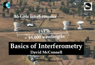
Basics of Interferometry David McConnell
260 likes | 413 Vues
This workshop presentation by David McConnell at the 2003 ATNF Synthesis Workshop delves into the basics of interferometry in radio astronomy. It explores coherence principles, practical interferometer outlines, and the role of spatial coherence functions. The discussion covers key simplifying assumptions, the nature of electromagnetic wave propagation, and the underlying mathematics governing interference patterns. Additionally, it highlights common challenges in sampling and image analysis. Aimed at both novices and practitioners, this resource provides an essential foundation for understanding interferometric techniques.

Basics of Interferometry David McConnell
E N D
Presentation Transcript
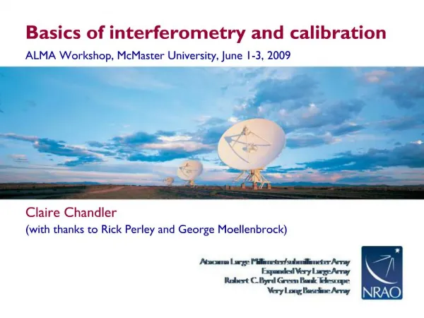
Basics of Interferometry David McConnell ATNF Synthesis Workshop 2003
Basic Interferometry • Coherence in Radio Astronomy • follows closely Chapter 1* by Barry G Clark • What does it mean? • Outline of a Practical Interferometer • Review the Simplifying Assumptions * Synthesis Imaging in Radio Astronomy II Edited by G.B.Taylor, C.L.Carilli, and R.A Perley ATNF Synthesis Workshop 2003
Interference Young’s double slit experiment (1801) ATNF Synthesis Workshop 2003
Object En(R) Wave propagation R Observer En(r) r Form of the observed electric field (1) Superposition allowed by linearity of Maxwell’s equations The propagator ATNF Synthesis Workshop 2003
Form of the observed electric field (2) Assumption 1: Treat the electric field as a scalar - ignore polarisation Assumption 2: Immense distance to source; ignore depth dimension; measure “surface brightness”: En(R) is electric field distribution on celestial sphere Assumption 3: Space is empty; simple propagator ATNF Synthesis Workshop 2003
Spatial coherence function of the field (1) Define the correlation of the field at points r1 and r2 as: where so ATNF Synthesis Workshop 2003
Spatial coherence function of the field (2) Assumption 4: Radiation from astronomical sources is not spatially coherent for R1R2 After exchanging the expectation operator and integrals becomes: ATNF Synthesis Workshop 2003
Write the unit vector as: Write the observed intensity as: Replace the surface element : Spatial coherence function of the field (3) ATNF Synthesis Workshop 2003
is known as the complex visibility. Spatial coherence function of the field (4) “An interferometer is a device for measuring this spatial coherence function.” ATNF Synthesis Workshop 2003
Write the components of s as Inversion of the Coherence Function (1) • The Coherence Function is invertible after taking one of two further simplifying assumptions: • Assumption 5(a): vectors (r1–r2) lie in a plane • Assumption 5(b): endpoints of vectors slie in a plane Choose coordinates (u,v,w) for the (r1–r2) vector space Then with 5(a): ATNF Synthesis Workshop 2003
s s0 is independent of w Inversion of the Coherence Function (2) Or, taking 5(b) assuming all radiation comes from a small portion of the sky, write the vector s as s = s0 + s with s0ands perpendicular Choose coordinates s.t. s0 = (0,0,1) then becomes ATNF Synthesis Workshop 2003
Inversion of the Coherence Function (3) ATNF Synthesis Workshop 2003
m v (u,v) l u Image analysis/synthesis (1) ATNF Synthesis Workshop 2003
m v m l u m l l Image analysis/synthesis (2) ATNF Synthesis Workshop 2003
Incomplete Sampling (1) Usually it is not practical to measure Vn(u,v) for all (u,v) - our sampling of the (u,v) plane is incomplete. Define a sampling function: S(u,v) = 1 where we have measurements, otherwise S(u,v) = 0. is called the “dirty image” ATNF Synthesis Workshop 2003
Incomplete Sampling (2) The convolution theorem for Fourier transforms says that the transform of the product of functions is the convolution of their transforms. So we can write: The image formed by transforming our incomplete measurements of Vn(u,v) is the true intensity distribution In convolved with B (l,m), the “synthesized beam” or “point spread function”. ATNF Synthesis Workshop 2003
Interferometry Practice (1) and therefore g change as the Earth rotates. This produces rapid changes in r(g) the correlator output. This variation can be interpreted as the “source moving through the fringe pattern”. ATNF Synthesis Workshop 2003
Interferometry Practice (2) We could introduce a variable phase reference and delay compensation to move the “fringe pattern” across the sky with the source (“fringe stopping”). ATNF Synthesis Workshop 2003
fLO1 t CORRELATOR Antennas (Ravi Subrahmanyan) amplification Receivers (Graeme Carrad) fLO2 fringe stopping fS2 fS1 Delay compensation and correlator (Warwick Wilson) delay tracking ATNF Synthesis Workshop 2003
SimplifyingAssumptions (1) Assumption 1: Treat the electric field as a scalar - ignore polarisation Polarisation is important in radioastronomy and will be addressed in a later lecture (see also Chapter 6). Assumption 2: Immense distance to source, so ignore depth dimension and measure “surface brightness”: En(R) is electric field distribution on celestial sphere In radioastronomy this is usually a safe assumption. Exceptions may occur in the imaging of nearby objects such as planets with very long baselines. ATNF Synthesis Workshop 2003
SimplifyingAssumptions (2) Assumption 3: Space is empty; simple propagator Not quite empty! The propagation medium contains magnetic fields, charged particles and atomic/molecular matter which makes it wavelength dependent. This leads to dispersion, Faraday rotation, spectral absorption, etc. Assumption 4: Radiation from astronomical sources is not spatially coherent Usually true for the sources themselves; however multi-path phenomena in the propagation medium can lead to the position dependence of the spatial coherence function. ATNF Synthesis Workshop 2003
SimplifyingAssumptions (3) • The Coherence Function is invertible after taking one of two further simplifying assumptions: • Assumption 5(a): vectors (r1–r2) lie in a plane • Assumption 5(b): endpoints of vectors slie in a plane 5(a) violated for all but East-West arrays 5(b) violated for wide field of view The problem is still tractable, but the inversion relation is no longer simply a 2-dimensional Fourier Transform (chapter 19). ATNF Synthesis Workshop 2003
Interference Young’s double slit experiment (1801) ATNF Synthesis Workshop 2003
CORRELATOR ATNF Synthesis Workshop 2003
CORRELATOR Finite bandwidth ATNF Synthesis Workshop 2003
Delay CORRELATOR Finite bandwidth Delay tracking ATNF Synthesis Workshop 2003