Download

1 / 11
110 likes | 259 Vues
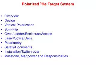
Creating and Measuring Very Uniform Magnetic Fields for a Polarized 3 He Target. University of North Carolina at Chapel Hill. Mark Fassler, Tatsuya Katabuchi, and Thomas B. Clegg,

E N D
Creating and Measuring Very Uniform Magnetic Fields for a Polarized 3He Target University of North Carolina at Chapel Hill Mark Fassler, Tatsuya Katabuchi, and Thomas B. Clegg, University of North Carolina at Chapel Hill and Triangle Universities Nuclear Laboratory (TUNL), Durham, NC, USA and John Nouls, Amersham Health, Research Triangle Park, NC, USA
Motivation • Seek to measure spin-correlation observables in p+ 3He scattering at energies between 2 and 5 MeV. • Need a polarized 3He target for such measurements. • Need a very uniform magnetic field to maintain 3He polarization in the target. • Experimental constraints dictated that a “Sine Theta” coil be used to create the magnetic field, and that this B-field should be uniform to better than 10-3 per centimeter.
Blue: outward Red: inward Max Sine-Theta Coil - Concept Current Direction • Variable surface current • Current I sin q • Required field uniformity • Mu-metal cylinder • Enhances B-field inside cylinder • Shields internal region from external fields. • Side apertures are possible
7.5 cm 5 cm mu-metal (1 mm thick) 24 current rods (3 mm diam) Sine-Theta Coil – B-Field Calculation • Poisson/Superfish LANL code used to calculate magnetic field from currents and magnetic properties • GeometryShielded infinite cylinder • Results A 5 cm diam central region has
Sine-Theta Coil – Design Details • 24 Copper rods placed on Delrin cylinder. • Six separate currents are regulated to 10-3. • Coil is covered with a mu-metal shield with windows for emerging scattered particles.
Sine-Theta Coil – Realization Assembled coil with rods and current carrying wires. Horizontal slot provided for scattered particles. Delrin cut horizontally. Mu-metal shield cut vertically.
Setup for B-field Measurement • The robot moved the Hall probe around inside the sine-theta coil. At regular spacings on a 3D grid, a computer with a 3D gaussmeter took measurements of the 3D B-field. • A typical scan produces thousands of data points, each with 6 dimensions of data – x,y,z, Bx, By, Bz 3-axis Hall probe 3-axis robot Wired sine-theta coil in mount
Visualizing the Data • The red arrows inside the sine-theta “coil” are actual data taken during a scan with the robot. Each arrow is a vector indicating the magnitude and direction of the B-field at a point in space. The B-field varies by less than 1% throughout the volume of interest, so differences are not visible when plotted in this way. To analyze variations which are important for the physics, we plot instead variations in the B-field.
x y • Transverse-component midplane contour maps (in Gauss) z By Bz Sine-Theta Coil – Measured B-Field • Currents adjusted to provide Bx = 10 Gauss • Scanned interior with a 3-axis Hall probe • Found < 2 x 10⁻³/cm
‘Flip Book’ of Cross Sections • These 18 pages (included on the next page as a short mpeg movie) show a sequence of cross-sections of the B-field in the sine-theta coil down the z-axis from about center – 3.8 cm to center + 3.8 cm. • The greatest irregularities are on the top and bottom. These are caused by joints between the two halves of the mu-metal. In particular, in the center along the top there is great irregularity along the z-axis, caused by holes in the mu-metal which provide clearance for the tubes for the 3He to enter and exit the cell. • Along the left side on can see slight B-field irregularities cause by holes in the mu-metal which allow the scattered particles to escape.