Plot Plans
Chapter. 15. Plot Plans. Introduction. Two types of plans show land how the building will be situated on it: Site plan A Site Plan is a (top) view drawing that shows the contours of the building site and location and orientation of any buildings on the property. Plot plan

Plot Plans
E N D
Presentation Transcript
Chapter 15 Plot Plans
Introduction • Two types of plans show land how the building will be situated on it: • Site plan A Site Plan is a (top) view drawing that shows the contours of the building site and location and orientation of any buildings on the property. • Plot plan The Plot Plan shows both the property and the proposed new construction.
Site Plan • Shows property lines and existing topography • Shows specific features, including: • Length and bearing of property lines • Land contour • Elevation of property corners and contour lines • Meridian arrow (north arrow) • Existing streets, driveways, sidewalks and patios.
Site Plan • Location, outline, size of existing buildings • Location of existing utilities • Easements for utilities and drainage • Existing fences and retaining walls • Trees, shrubs, streams, gardens • Lot number or address • Drawing scale
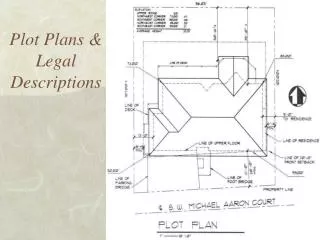
The Plot Plan The Plot Plan is developed from site plan. Information is provided by surveyor. The Plot Plan Shows proposed new construction on site.
Property Lines • Property lines define site boundaries • Length and bearing of each property line are identified on site plan • Begin at one corner and work clockwise around site
Bearings Bearings are measured from north or south and may include degrees, minutes, and seconds.
Benchmark A Benchmark is a permanent object used by surveyors to establish points of reference. The lower left corner of the property is on a benchmark, so it is identified with a benchmark symbol.
Contour Lines • Contour Lines help describe the topography of site by depicting shape and elevation of land. • Contour Lines Connect points that have same elevation. • Contour interval is vertical distance between two adjacent contour lines.
Contour Lines • Spacing of contour lines represents slope of land. • Smoothness of contour lines represents roughness of land. • Summits and depressions represented by closed contour lines. • Different elevation lines do not cross. • Accepted reference elevation point for topographical surveys is mean sea level.
Contour Lines This illustration shows a five foot contour interval.
Contour Lines The relative space of contour lines represents the slope angle.
Contour Lines Contour lines show relative roughness of the land as well as the elevation.
Topographical Features • Topographical features are represented by standard symbols and nonstandard symbols. • Standard symbols and Nonstandard symbols are identified in a legend.
Locating the Structure First method of locating a structure on a plot plan is to lay out the outside of the exterior walls, omitting all interior walls and roof.
Locating the Structure Second method of locating a structure on a plot plan is to draw the exterior walls as hidden lines and show the roof using solid lines.
Locating the Structure Third method of locating a structure on a plot plan is to show the exterior walls thickened.
Locating the Structure The simplest way to highlight a structure is to crosshatch the entire building area or hatch around the perimeter of the structure. The overall representation of the structure should conform to the overall style of the drawing and the other symbols used.