Download
1 / 74
740 likes | 878 Vues
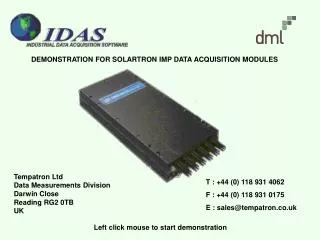
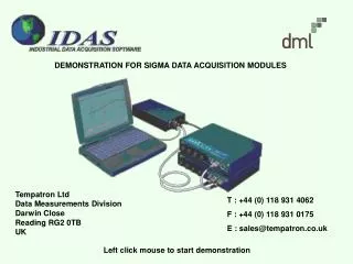
DEMONSTRATION FOR SIGMA DATA ACQUISITION MODULES. Tempatron Ltd Data Measurements Division Darwin Close Reading RG2 0TB UK. T : +44 (0) 118 931 4062 F : +44 (0) 118 931 0175 E : sales@tempatron.co.uk. Left click mouse to start demonstration. MAIN MENU WINDOW.

E N D
DEMONSTRATION FOR SIGMA DATA ACQUISITION MODULES Tempatron LtdData Measurements DivisionDarwin CloseReading RG2 0TBUK T : +44 (0) 118 931 4062 F : +44 (0) 118 931 0175 E : sales@tempatron.co.uk Left click mouse to start demonstration
MAIN MENU WINDOW Select Devices to set up the measurement devices on the network.
DEVICE SELECTION Select type of data logging equipment in use. iDAS is compatible with both Tempatron’s Sigma system and Solartron IMPS. This demonstration covers the Sigma system only. The correct driver must be installed for each type of equipment. In this case select Sigma.
MODULE CONFIGURATION - SIGMA This screen shows the modules that are available on the network. To view the modules connected to the network, select Edit - Network Modules (or click on the network icon). iDAS will then search the network and interrogate all modules found.
MODULE CONFIGURATION - SIGMA This screen shows the modules that are available on the network. To view the modules connected to the network, select Edit - Network Modules (or click on the network icon). iDAS will then search the network and interrogate all modules found.
MODULE CONFIGURATION - SIGMA Note : To speed up the network search, reduce the number of modules from 100 to 5. Click on OK to continue.
MODULE CONFIGURATION - SIGMA All modules found on the network will be displayed in the resulting window. The module’s details can be transferred into iDAS by clicking on Read. Clicking OK returns to the module configuration screen
MODULE CONFIGURATION - SIGMA All modules found on the network will be displayed in the resulting window. The module’s details can be transferred into iDAS by clicking on Read. Clicking OK returns to the module configuration screen
MODULE CONFIGURATION - SIGMA The modules located on the network can now be configured. Select Edit – Configure Module, click the Configure Module icon, or double click on the module in the list.
MODULE CONFIGURATION - SIGMA The modules located on the network can now be configured. Select Edit – Configure Module, click the Configure Module icon, or double click on the module in the list.
MODULE CONFIGURATION - SIGMA Select the module type (if it has not already been set by the Read command).
MODULE CONFIGURATION - SIGMA Select the module type.(use 310a for this demo)
MODULE CONFIGURATION - SIGMA The network address, acquisition rate and other module parameters can be set at this stage. To configure the individual channels in the module, highlight the channel (SA1 here) and click on Configure Channel or double click the highlighted channel.
CHANNEL CONFIGURATION - SIGMA Click on Enable Channel to set up theoperating parameters for each input channel.
CHANNEL CONFIGURATION - SIGMA The identification and operating parameters for each input channel can then be set up, including the measurement type, scale and units as well as alarm parameters. Each input channel to be used should be set up in this way. For convenience the Copy and Paste facility can be used. Click anywhere in the window to insert example values.
CHANNEL CONFIGURATION - SIGMA When all of the parameters are correctly set, click on the OK button to return to the channel selection screen
MODULE CONFIGURATION - SIGMA When all the required channels are set, click the OK button to return to the module configuration screen.
MODULE CONFIGURATION - SIGMA To save the module configuration, select File – Save or click the save icon.
MODULE CONFIGURATION - SIGMA To save the module configuration, select File – Save or click the save icon.
MODULE CONFIGURATION - SIGMA Close this screen (File – Exit or x) to complete configuration of the modules connected to the system.
MODULE CONFIGURATION - SIGMA Close this screen (File – Exit or x) to complete configuration of the modules connected to the system.
SET UP IDAS INTERNAL CHANNELS Select Processors to set up iDAS “internal” channels.
PROCESSORS – USER ANALOGUE CHANNELS User Analogue channels are "internal channels" that can be used in many ways. They can be used to hold manually input values, entered via the Channel Monitor Window, such as a set point or coefficient value required by an algorithm configured in the System's Calculator package. They can also hold the results of calculations performed by the Calculator package. Once configured User Analog Channels have the prefix 'P' and can be monitored, logged and replayed in the usual way. Select menu item to see its applications. Click x to return to the main menu
PROCESSORS – USER DIGITAL CHANNELS The User Digital channels are "internal channels" that can be set ON or OFF in a number of ways. Using the channel monitor window the status of the User Digital channels can be changed by selecting the channel and pressing the spacebar. User Digital Channels can also be used as 'flags' in Calculator Algorithms Once configured, User Digital Channels have the prefix ‘Q' and can be monitored, logged and replayed in the usual way. Select menu item to see its applications. Click x to return to the main menu
PROCESSORS – HISTORY CHANNELS The History processor provides a short term history over a user defined time period for up to 33 System Channels. The history of any System channel is recorded by a block of 30 contiguous channels given the prefix 'H'. The main use of these channels is to animate mini-trends in the Visual Environment animation package. History channels can also be used to provide a lag function in control algorithms. Select menu item to see its applications. Click x to return to the main menu
PROCESSORS – DATA EXCHANGE Data can be exchanged with other software packages using the OpDdx Processor. This system is a data capture client that can connect to multiple OPC Servers and/or multiple DDE Servers. There are up to 1000 OpDdX channels available and they have the prefix 'D'. OpDdx Channels can be configured to cause events and alarms and can be monitored and logged like any other System Channel. Select menu item to see its applications. Click x to return to the main menu
PROCESSORS – SYSTEM ERROR CHANNELS The System Error processor allows the user to Enable a set of channels which will report any errors that occur in the system and, if necessary, will generate alarms, or drive a common alarm. Select menu item to see its applications. Click x to return to the main menu
PROCESSORS – CALCULATED CHANNELS The Calculator channels allow real-time calculations to be performed on data being collected by the System. Calculator channels are analogue channels whose value is calculated from a user specified formula. Any System channel can be used as part of a calculation, both digital or analogue, input or output. There are up to 1000 calculator channels available and have the prefix 'C'. Calculator Channels can be configured to cause events and alarms and can be monitored and logged like any other System Channel. Select menu item to see its applications. Click x to return to the main menu
PROCESSORS – ALARM SYSTEM The alarm system processor is used to configure the alarms previously set up in channel configuration. The system will allow alarms to be printed, saved to log files and annunciated using SMS text messaging or via e-mail. Select menu item to see its applications. Click x to return to the main menu
ENABLING THE SYSTEM To enable iDAS data acquisition, select Control – Enable or click the enable icon. iDAS will commence reading (but not logging to disk) the input data. iDAS data loggers have to be set up and enabled for data logging to commence.
ENABLING THE SYSTEM To enable iDAS data acquisition, select Control – Enable or click the enable icon. iDAS will commence reading (but not logging to disk) the input data. iDAS data loggers have to be set up and enabled for data logging to commence.
SYSTEM ENABLED – MONITOR INPUT CHANNELS iDAS is now running and will continue to read the input data until it is disabled. To continuously view the input data, select Monitors – Channel Monitor – Configure.
SYSTEM ENABLED – MONITOR INPUT CHANNELS iDAS is now running and will continue to read the input data until it is disabled. To continuously view the input data, select Monitors – Channel Monitor – Configure.
SYSTEM ENABLED – MONITOR INPUT CHANNELS iDAS is now running and will continue to read the input data until it is disabled. To continuously view the input data, select Monitors – Channel Monitor – Configure.
SYSTEM ENABLED – MONITOR INPUT CHANNELS This screen allows the data source and display formats to be set up. For this demo, select Sigma and click OK.
SYSTEM ENABLED – MONITOR INPUT CHANNELS The channel monitor is now showing the input data as it is measured. Note this data is not being logged to disk at this stage. This window should be closed or minimised so that the iDAS data loggers can be set up. Click on x to close the window and continue.
SYSTEM ENABLED – MONITOR INPUT CHANNELS The channel monitor is now showing the input data as it is measured. Note this data is not being logged to disk at this stage. This window should be closed or minimised so that the iDAS data loggers can be set up.
SET UP IDAS DATA LOGGERS Select Loggers to set up and enable iDAS data loggers to record the input data to disk.
LOGGER CONFIGURATION - SIGMA Click on the logger to be set up (Logger 1 for this example).
LOGGER CONFIGURATION - SIGMA The General window is used to set the logger name, type, logging rate, start mode, start and stop times if required and cycling modes. To determine the channels to be logged to disk, click on the Channels tab.
LOGGER CONFIGURATION - SIGMA Click on the Channels box to set up the channels to be logged to disk.
LOGGER CONFIGURATION - SIGMA Select the input channel type (Sigma for this example) and enter the range of channels to be logged to disk.
LOGGER CONFIGURATION - SIGMA Enter the channel numbers to be logged (Sigma channels 1-10 in this example) and click on the OK button to continue. To delete channels click on Clear.
LOGGER CONFIGURATION - SIGMA Any combination of channels can be set for any of the loggers available in iDAS. Changes to the logger configuration must be saved by clicking on File –Save or on the disk icon.
LOGGER CONFIGURATION - SIGMA Any combination of channels can be set for any of the loggers available in iDAS. Changes to the logger configuration must be saved by clicking on File –Save or on the disk icon.
ENABLE LOGGER - SIGMA To start the logger recording input data to disk, select Control – Enable or click on the enable icon. To stop the logger at any time, select Control – Disable or click the disable icon.
LOGGER CONFIGURATION - SIGMA To start the logger recording input data to disk, select Control – Enable or click on the enable icon. To stop the logger at any time, select Control – Disable or click the disable icon.
LOGGER CONFIGURATION - SIGMA The Logger configuration is now complete and the window can be closed – select File – Exit or click on x.
LOGGER CONFIGURATION - SIGMA The Logger configuration is now complete and the window can be closed – select File – Exit or click on x.
CONTROLLING IDAS DATA LOGGERS To control iDAS data loggers, select Loggers – Control Loggers