Download
1 / 23
240 likes | 422 Vues
MRB on SLAC NCR 226 MCM Encapsulation Delamination. R.P. Johnson January 3, 2005. Contents. Description of the nonconformance Overstress analysis and additional testing Suspected root cause Impacts to inventory Corrective action Effectiveness of corrective action Recommended disposition.

E N D
MRB on SLAC NCR 226MCM Encapsulation Delamination R.P. Johnson January 3, 2005
Contents • Description of the nonconformance • Overstress analysis and additional testing • Suspected root cause • Impacts to inventory • Corrective action • Effectiveness of corrective action • Recommended disposition MRB, SLAC NCR 226
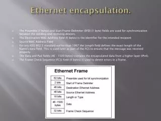
1. Description of Non-Conformance • Item: MCM part number LAT-DS-00898 and LAT-DS-00899. • Nonconformance: >40 MCMs have been rejected at SLAC because they each have >15 channels disconnected between the ASICs and pitch adapter or >0 disconnected bias traces. This is ~15% of MCMs tested. • Some additional loss of channel connections has occurred on MCMs already integrated onto trays. • The vast majority of the loss of channels is from delamination of the epoxy encapsulation from the Kapton pitch-adapter flex circuit. MRB, SLAC NCR 226
34% have zero disconnected channels 79% have <9 disconnected channels out of 1536 (0.5%) 85% have <16 disconnected channels out of 1536 (1%) 10% have more than 50 disconnected channels! The worst case has 750 disconnected channels (50%)! Number of Disconnected Channels MRB, SLAC NCR 226
Location of Disconnected Channels • The disconnected channels are most likely to occur toward the MCM center. MRB, SLAC NCR 226
Time Distribution of the Problem • Before July 1 the disconnected channels are few and are consistent with being mostly from cracked traces. • After July 1 we started seeing MCMs with huge numbers of missing connections. • This time dependence is not understood. Teledyne claims that there was no corresponding change to process or personnel. MRB, SLAC NCR 226
Delamination During MCM Mounting • 4 Tower-A MCMs suffered visible delamination of the encapsulation while mounting the MCMs onto trays at G&A. • These were MCMs with essentially zero broken wire bonds when tested at SLAC. • In 3 of the cases the MCM was delivered to SLAC before July 1. • The delamination was generally near the MCM end, in the controller-chip region. • This effect may have a similar root cause to NCR 226, in terms of poor encapsulation adhesion. • However, the problem was eliminated in Tower B by • Modified procedure to attach the MCM to the jig. • Less adhesive for MCM mounting; hence less force on the MCM from the jig. 142 consecutive wire bonds are broken! Visible gap MRB, SLAC NCR 226
Mounting MCMs onto Trays • The MCM is clamped with the pitch-adapter pushed against a straight jig, to ensure a straight top edge for wire bonding. • Custom pins clamp the rest of the board to the jig and also have a thin washer to guarantee the adhesive bond line. • The jig precision aligned to the tray, gluing the MCM to the tray with a venting pattern of 3M 2216 epoxy. MCM Tray Panel MRB, SLAC NCR 226
2. Overstress Analysis & Additional Testing • Preproduction MCMs used for qualification did not show any problems with wire bond breakage after 220 thermal cycles from 30C to +85C. • This suggests that it is possible to make the encapsulation work, so that a design change may not be necessary if process problems can be solved. MRB, SLAC NCR 226
Thermal Cycles of Flight MCMs • All MCMs get 21 thermal cycles from 30C to +85C. • We have data before and after thermal cycles for only 21 MCMs. • The large-scale breakage appears to occur during these cycles. MRB, SLAC NCR 226
CSAM (acoustic microscopy) Test Results • High frequency (~40 MHz) sonar reflected images show in red delamination of the black Hysol epoxy encapsulation from the Kapton pitch adapter. Chip 0 • SN 600, delivered May 23, has no disconnected channels (zero broken wire bonds). Nevertheless, the left-hand end shows substantial delamination. • SN 11046, delivered September 1, has 362 disconnected channels, all on the right-hand 1/3 of the MCM. In that region the delamination approaches 100%, as dose the percentage of broken wire bonds. MRB, SLAC NCR 226
3. Suspected Root Cause • The delamination occurs during thermal and/or mechanical stress. • However, good bonding to the pitch adapter may be enough to withstand the stress, so the bonding process is suspect. • Thermal Strain: • Height of the vertical cliff (raised strip on the PWB): 0.55 mm • Temperature range from cure (125 C) to the thermal-cycle low (30 C): 155 C • CTE mismatch between the PWB and encapsulation along the cliff: 37 ppm • Strain: 37×106 ×155 = 0.57% • Relative displacement if free: 0.0057×0.55 mm = 0.003 mm = 3 microns MRB, SLAC NCR 226
X-Ray Cross Section of an MCM Encapsulation Fill Encapsulation Dam Wire Bond Flex Circuit ASIC and Conductive Glue The “Cliff” Internal Cu Planes Fiberglass MRB, SLAC NCR 226
Stress Analysis The FEM shows the expected stress at the cliff, where the CTE mismatch is. But it is not quantitatively conclusive, since we do not know at what stress this bond will fail. If the bond along the cliff failed, then we would expect the pitch adapter to start to peel away from the encapsulation starting at the corner. Corner Pitch adapter cliff MRB, SLAC NCR 226
Chip 12 Section, bond 30S/N 775 Wire bond fracture Delamination Delamination Copper trace Circuit board Destructive Physical Analysis Diane did not see evidence of delamination on the “cliff”. 25 m Al wire • The wire bond is lifted up by the delamination. • The foot remained welded to the copper trace, so the bond broke. • In the case of broken bonds, the delamination extends all the way to the dam, as seen in the CSAM images MRB, SLAC NCR 226
Silicone Contamination • NASA QA noticed last autumn that the Teledyne Kapton masking tape had a silicone-based adhesive. • This was found at the time of the production stop, so as far as we know, all MCMs built to date used this masking tape. • Prior to soldering, the pitch adapter was covered 100% by that tape. • The tape remained on in the reflow oven and during vapor degreasing afterwards. • The pitch adapter was wiped with acetone and alcohol afterwards, and plasma cleaning was done before wire bonding. • NASA found evidence of silicone residue at the encapsulation-pitch-adapter interface during DPA of MCM S/N 775. • From experience, even a thin residue of silicone can prevent proper bonding of epoxies, so this is the leading hypothesis for the failure of the encapsulation. MRB, SLAC NCR 226
4. Impacts to Inventory • 72 MCMs have been mounted on Tower-A and Tower-B trays. • Enough MCMs remain for 3 more complete towers. • Part of a 6th tower could also be equipped. • Changing the requirement from <16 broken wires to <9 broken wires would eliminate an estimated 18 MCMs, including at least one tall. This may still allow 5 towers to be equipped. MRB, SLAC NCR 226
5. Corrective Action • MCM screening at SLAC • 100% test of all signal and bias traces on the existing stock following thermal cycles and burn-in. Reject all MCMs with >15 dead or disconnected signal channels or with >0 disconnected bias traces. • MCM mounting at G&A • Mount the MCM to the jig very carefully, working from center outward. • Reduce the amount of adhesive, so that less pressure is required on the MCM and pitch adapter to squeeze it down. • Visually inspect for delamination using a microscope before committing SSD ladders to the tray. Pitch-Adapter Test Fixture MRB, SLAC NCR 226
Corrective Action • New Teledyne production • Eliminate the tape with silicone adhesive from the production line (done). • Procure tape with acrylic adhesive and test that it really is acrylic (done). • Clean the MCM tooling with acetone and use a water-break test to ensure that the tooling surfaces are not contaminated (done). • Implement the 100% test of the pitch-adapter connections at the MIP-3 stage (the second test fixture has been procured). • Develop a back-up plan using fiberglass covers in place of encapsulation, in case the encapsulation continues to fail (in progress). • Environmental testing • Change the Tower qualification test lower limit from 30C to 20C and the acceptance test lower limit to 15C. • This change was made because of ladder issues, but it also helps reduce stress on the MCMs. • Change the MCM test range to 25C+60C, still with 20 cycles. Burn-in remains +85C for 168 hours. MRB, SLAC NCR 226
6. Effectiveness of Corrective Action • The worst delaminations on Tower-A were caused by stress from MCM mounting. Those delaminations propagated up to 50% during thermal testing. • New procedures prevented breakage during mounting for Tower-B. • The SLAC screening was mostly effective, but in a couple of cases small existing regions of broken wire bonds expanded by up to 70%. • Vibration had no effect in any case. The table shows the wire-bond breakage history for all flight layers with >8 disconnected channels. MRB, SLAC NCR 226
Effectiveness of Corrective Action Flight Tower Quality: • Tower A: • 3 of 36 SSD layers have >2% disconnected channels in the MCM. • Other problems exist in connections within some ladders on heavy trays (subject of a different NCR). • Only 5 of 36 SSD layers on the tower have <98% efficiency for detection of a minimum-ionizing particle. • The average efficiency over all layers is 98.7%, so while some individual layers do not meet our goal of 98%, on average we satisfy our goal. • Monte-Carlo studies show negligible impact on science even with all 16 towers having this degree of inefficiency. • Tower-B: • After tray thermal cycles and testing of stacked trays, the worst case is a 1.8% loss of MCM channels in a single layer. • Assuming little change in tower environmental testing, we can anticipate a tower with all layers having >98% efficiency and an average efficiency >99%. MRB, SLAC NCR 226
Effectiveness of Corrective Action • New MCM production • We have no results yet, but our goal is to eliminate wire-bond breakage from delamination of encapsulation. (There probably will be some residual loss of channels from cracked pitch-adapter traces, but that problem has not been observed to increase during environmental testing.) • We are setting up a plan to bond and wire bond non-flight chips to some PWBs immediately, followed by encapsulation and then CSAM before and after thermal cycles for verification. • The first batch of ~25 MCMs will undergo qualification testing: • Complete MCM thermal-cycle and burn-in routine, followed by the 100% electrical test. • Send at least 2 MCMs for CSAM. We assume that they will have no broken wire bonds. • Thermal cycle at least 2 MCMs 200 times, followed by the 100% electrical test. MRB, SLAC NCR 226
7. Recommended Disposition • Scrap (use for EGSE) MCMs with >15 bad channels (dead or disconnected) or >0 disconnected bias traces. • After this screening, use the remaining stock of MCMs for flight towers A, B, 1, 2, and 3, subject to success in all other tests and inspections. • Continue using the MCM mounting procedures that were successful in Tower-B trays. MRB, SLAC NCR 226