Download
1 / 25
360 likes | 656 Vues
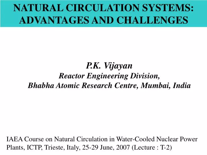
NATURAL CIRCULATION SYSTEMS: ADVANTAGES AND CHALLENGES. P.K. Vijayan Reactor Engineering Division, Bhabha Atomic Research Centre, Mumbai, India. IAEA Course on Natural Circulation in Water-Cooled Nuclear Power Plants, ICTP, Trieste, Italy, 25-29 June, 2007 (Lecture : T-2). COURSE ROADMAP.

E N D
NATURAL CIRCULATION SYSTEMS: ADVANTAGES AND CHALLENGES P.K. Vijayan Reactor Engineering Division, Bhabha Atomic Research Centre, Mumbai, India IAEA Course on Natural Circulation in Water-Cooled Nuclear Power Plants, ICTP, Trieste, Italy, 25-29 June, 2007 (Lecture : T-2)
OUTLINE OF THE LECTURE T#2 • INTRODUCTION - WORKING PRINCIPLE OF NCS - APPLICATIONS OF NCS - ADVANTAGES OF NCS - CHALLENGES OF NCS - CLASSIFICATION OF NCS - TERMINOLOGIES USED IN NCS - CLOSURE
Cooler Heater Thermosyphon loop Gas Separator Gas Mixer Adiabatic NCL Introduction to NCS Fluid-filled systems with buoyancy-induced circulation caused by density gradients is known as NCS. The density gradient can be caused thermally (thermosyphon loops) or adiabatically by the injection of a low density fluid (adiabatic NCS). A heat source and a heat sink connected by pipes form the essential hardware of thermosyphon loops A mixer and a separator connected by pipes form the essential hardware of adiabatic NCLs (e.g. gas lift pumps). Circulation is established in the loop without any fluid moving machinery. High reliability as the driving mechanism is based on a natural physical law. Both type of NCSs have extensive application in conventional and nuclear industries. In this talk we limit our attention to thermosyphon loops.
Natural Circulation cooling in Cray Computer Espresso Coffee Machine CPU Cooling in PCs Application of NCS Traditional applications: solar water heaters, geothermal power extraction, coffee machines,coolingof transformers, rotating machinery, nuclear reactors, etc. An Emerging field of application is the cooling of computer systems. NCSs for computer cooling can be made with very low inventory of working fluid. Also, the heat transport capability of such loops can be as low as a few hundred Watts.
WORKING PRINCIPLE OF NCS cooler ρc ρh H Heater a b Due to the difference in densities between the vertical legs, a pressure difference is created between stations a and b which is the cause of the flow. At steady state the driving buoyancy force is balanced by the retarding frictional force thus providing a basis for the estimation of the flow rate. Natural circulation flow is enhanced by the loop height and the difference in densities
BRIEF HISTORY OF NCS Steam Condensate NCB in FPP Thermosyphon Reboiler First large scale use of NC systems appears to have been in the automobile industry. Such systems were in use till the 1940s. NCSs find extensive use in chemical and power generation industries - Thermosyphon reboilers - Natural circulation boilers (NCB) NCBs of capacity up to 660 MWe are in operation today. NCBs are capable of similar thermal performance compared to ACBs, economically competitive with less operation and maintenance cost. Even 900 /1000 MWe plants use 2 or 3 NCBs rather than an assisted circulation boiler (ACB).
Natural circulation in Nuclear Industry Single-phase NC -Current PWRs and PHWRs are designed to remove decay heat by NC in the event of a CLOP -For existing PWRs as much as 20 % FP can be removed by single-phase NC -District heating reactors upto 500 MWt based on single-phase NC are operational -CAREM is a PWR being developed by Argentina 1 – reactor core 2 – core barrel 3 – steam generators 4 – guard tube block shroud 5 – reactor pressure vessel 6 – reactor closure head -High temperature reactors are required for enhancing thermal efficiency as well as for hydrogen production. Many of the high temperature reactor concepts prefer NC (e.g. LFR) -NC reactor designs are being proposed even for SCRs(CANDU–X-NC and BF-500SKDI) The BF500 SKDI reactor
Natural circulation in Nuclear Industry – Contd. NC SG Two-phase natural circulation NC based steam generators of rating around 1000 MWt are extensively used in PWRs, PHWRs and VVERs NC is the preferred circulation mode for steam generation in conventional as well as nuclear industry Two-phase NC based Reactors (NBWRs) Humboldt Dodewaard VK-50 ESBWR VK-300 AHWR Bay 3, USA Netherlands Russia GE Russia India 63 MWe 65 50 1380 250 300 1963-76 1969-97 Op. PAR Designed PLR Many new designs under development like the ESBWR, AHWR and VK-300 are also based on two-phase NC. The Indian AHWR is the only one using the pressure tube concept.
ADVANTAGES OF NATURAL CIRCULATION Reduced cost due to the elimination of pumps - Capital, operating and maintenance costs are low Improved flow characteristics and distribution - NC flow increases with power - FC flow decreases with power in the two-phase region - NC can handle power maldistribution better than FC Improved safety characteristics due to low power density and large coolant volumes - All safety issues associated with pump failure are eliminated - NC is based on a natural physical law and is not expected to fail - All transients become sluggish - Large boil-off times Simplicity in design and layout - Factory fabrication possible with better quality control
CHALLENGES FACING NCS The NC based power reactors (Humbholdt Bay, Dodewaard and VK-50) are more or less of the same power rating and vintage. Although, NCSs are well-proven in the fossil-fired power plants, their use in reactor systems has been limited. Several innovative designs based on two-phase natural circulation are being pursued by several countries Large scale deployment of NCRs are also hampered by certain characteristics of NCSs
CHALLENGES FACING NCSs – Contd. Low driving force • Due to the use of tall risers NCRs are slender in structure, which may raise economic & • seismic concerns (AHWR:40m; PHWR:35m) • - Low system pressure losses • (a) Larger diameter of components leading to large coolant inventory • (AHWR:330T; PHWR-220:70 T) • (b) Elimination of mechanical separators can increase carry over and carry under. • Increased carry under lowers both thermal as well as stability margin. Gravity • separation may require large steam-water interface area and hence vessel. • (c) Simplified piping and equipment layout • -Low mass flux ~400-1100 kg/m2s (2000-4000 kg/m2s) • (a) Low channel power leading to larger core size for the same power rating • (RPV of VK-300 VVER-1000; CV AHWR ~ PHWR-540) • (b) Larger core size can lead to problems in reactor control • (c) Loosely coupled regions in large core can induce zonal neutronic oscillations
CHALLENGES FACING NCSs – Contd. • Low CHF • - Core size optimization results in large exit quality • - CHF enhancement techniques are desirable for power uprating • Instability Effects • NCSs are inherently less stable than forced CSs • - Differences exist in the orificing to match power and flow • - Conventional stabilizing techniques like inlet orificing does not always work. • Loop liquid continuity is desirable under all conditions to • have smooth natural circulation flow at all powers • (a) Inventory management procedures to accommodatethe swell and shrinkage due • to void formation and collapse required • (b) Level control program required.
CHALLENGES FACING NCSs – Contd. -Start-up with stagnant coolant at low pressure (a) Low pressure low flow (LPLF) regime is important (b) Identifying suitable thermal-hydraulic correlations could be an important design activity -Specification of a start-up procedure - Avoidance of static and dynamic instabilities at low pressure - Minimize inventory transfer during heat-up - Selecting a suitable power and pressure raising procedure -Specification of an operating procedure - The entire operating domain shall be stable - Selecting a power raising procedure to avoid instabilities - The complete operating procedure to be established
CLASSIFICATION OF NCSs Bases for classification - State of the working fluid - Interaction with the surroundings - Shape of the loop, - Body force field - System inventory - Number of heated channels State of the working fluid -Single-phase NC - Two-phase NC - Supercritical NC
CLASSIFICATION OF NCSs - Contd. • - Single-phase NCS : Single-phase conditions prevail throughout • - Decay heat removal in PWR, PHWR, VVER and FBR following a CLOP • - District heating reactors (AST-500, NHR-200) • - CAREM: 27 MWe • - Cooling of canisters containing radioactive waste • - Cooling of ventilation system filters following power failure • Two-phase NCS: At least a part of the NCS experience two- • phase conditions • - Diabatic (boiling/condensing) or adiabatic systems • - Two-phase NC occurs following a CLOP in BWRs, or at reduced • inventory conditions in PWRs, PHWRs, etc. • - Two-phase NC is capable of generating larger flows • - Steam generation in conventional and nuclear industry • - Operating experience exists with NC BWRs of smaller rating • - Several new designs have been proposed
CLASSIFICATION OF NCSs - Contd. - Supercritical NCS - Large change in the thermal expansion coefficient near the critical point - Larger efficiency (~ 40%, Peak flow rate at ~ 400oC) - Excellent heat transfer characteristics of SCW - CANDU-X and B-500 SKDI are some concepts Interaction with the surroundings - Closed loop NC (Only exchange energy with the surroundings) - Open-loop NCS (exchange energy as well as mass) - Used in ship based reactors, research reactors, BWRs and NC SGs, thermosyphon reboilers, - NCSs for geothermal heat extraction, waste storage and surveillance facilities, ventilation systems etc.
CLASSIFICATION OF NCSs - Contd. cooler cooler U-tube heater Cooler-1 Cooler-2 Cooler cooler Heater-1 Heater heater Heater-2 Rectangular Figure-of-eight Toroidal Based on the shape of the loop
CLASSIFICATION OF NCSs - Contd. Radial limb Heated section Cooled section Body Force Field - Gravitational: - Stationary NCS - Centrifugal: - Rotating NCS A rotating closed loop NCS
CLASSIFICATION OF NCSs - Contd. Based on the System inventory - single-phase NCS - Two-phase NCS - Reflux condensation/boiling Based on the number of heated channels - Single channel loops - Parallel channel loops . Reactor systems, SGs, NCBs, etc.
Terminologies used in NCS sink Steam Hot leg source riser Feed heater downcomer Cold leg Hot leg, Cold leg, Riser, Downcomer
Terminologies used in NCS – Contd. Recirculation ratio, Inlet subcooling, inlet and exit orificing Steam Outlet orificing Feed heater Inlet orificing
Terminologies used in NCS – Contd. A1 A2 unstable stable unstable stable stable unstable power power stable unstable Inlet subcooling Inlet subcooling Decay Ratio, Stability map, Islands of stability and instability DR= A2/A1 ; DR < 1 Stable; DR = 1 neutrally; DR > 1 unstable Island of instability Island of stability
CLOSURE Brief History of NCS and their various applications - Thermosyphon reboilers, - NCB in fossil-fuelled power stations, - Nuclear SGs The main advantages of NCSs are highlighted - Economics, Flow characteristics, Safety aspects, Simplicity Challenges of NCS - Low driving force and its associated problems - Low CHF - Instability effects - Start-up and power raising procedure Classification of NCS and common terminologies used in NCS