Download
1 / 30
340 likes | 646 Vues
SCE-MI Integrating Emulation in a system level design methodology. San Jose’, 14/11/2003 Author: Andrea Castelnuovo Dynamic Verification Team Company STMicroelectronics. Summary. Transaction level modeling The Interoperability Gap SCE-MI: where, when Some use models

E N D
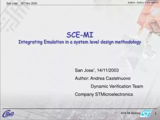
SCE-MI Integrating Emulation in a system level design methodology San Jose’, 14/11/2003 Author: Andrea Castelnuovo Dynamic Verification Team Company STMicroelectronics
Summary • Transaction level modeling • The Interoperability Gap • SCE-MI: where, when • Some use models • Expected Performances • Conclusions
SoC Simulation for Embedded SW Development • The Problem • Need SoC simulation platform even before RTL • Need simulation speed > 1000x faster than RTL • Need represent concurrency, interrupts etc • Cycle-Accurate (CA) model not appropriate • Solution: Transaction-Level Model (TLM) Courtesy of F Ghenassia
Transaction Level Modeling • Reference system model, including tesbench environment • Fast executable description for a system under development • Register accurate description for early and consistent software development Courtesy of F Ghenassia
software team verification team TLM model algorithm team design team A single SoC/IP executable reference model • Single reference model enables • Rationalizing modeling efforts • Consistency between developments • Communication between teams Courtesy of F Ghenassia
Motivations • Provide an infrastructure to support the Transaction Level Modelingmethodology • Objective of TLM models • Early embedded software development • Early (micro-)architecture analysis • Functional verification • Rely on anopen and tool-independentstandard • Activity started in ST/Central R&D in January 2000 (Frank Ghenassia) Courtesy of F Ghenassia
Transaction Level Model:Definitions • A system model is composed of a set of modules, that: • Execute part of the expected system behavior thanks to one or several concurrent threads • Communicate data between each other. • Each data set is called a transaction • Data sets of variable size • Synchronizebetween each other. A system synchronization is an explicit action Courtesy of F Ghenassia
PLL1 PLL2 JTAG / Trace Timers GPIO x76 Power Management ARM 926 EJ Watchdog SSP RTC UART x2 DDR/SDRAM Controller Sys.Ctrl. MSP (AC97,I2S,SPI) ICache DCache Interrupt Controller FIrDA NAND/NOR FLASH Ctrl Bridge SD/MMC I2C x2 Bridge eSRAM Buffer Color LCD Ctrl Display I/F RAM/ROM Secured 16 Channel DMA Ctrl Audio Smart Accelerator Video Smart Accelerator Camera I/F USB OTG TLM SoC development platform Courtesy of F Ghenassia
TLM: Interoperablility As soon as some RTL becomes available in the design flow, there is a need for interoperability between different abstraction layers. This is usually achieved by using proprietary interfaces, that allow linking two different environments. ?API? Transaction Any lower level decription: RTL, GATE, Cycle accurate behavioral
Modeltech BOOM !! TestBuilder vcs BOOM !! Specman NcVerilog Vera xsim Aptix C++ AXIS TLM Celaro Coware Other env Palladium VStation Other Boxes… Zebu Interoperablility becomes an issue
Interoperability issue • Every EDA vendor possibly provides a solution to interface its technology to external environments • The effort needed to create interfaces is too high compared to the business improvement that it could generate. This translates into intrisicly inefficient interfaces. • To efficiently interconnect hardware emulators to a transaction level environment, the user has to build synthesizable “transactors” for each specific interface. Transactors reusability is mandatory.-> the interface must be a standard
Modeltech TestBuilder vcs Specman NcVerilog Vera xsim Aptix C++ AXIS SystemC Celaro Coware Palladium VStation Other Boxes… Zebu SCE-MI: a clean approach SCE-MI
SCE-MI Use model SCE-MI SW RTL DESIGN SCE-MI infrastructure EDA Vendors Transactors designers End User
Transactors development • Transactors provide a translation gasket between a transaction level and the cycle-accurate pin level. • They are composed of two blocks: • “Software” layer: is the transactional side of the interface, which is also the master of the communication • “Hardware” layer: it contains the implementation of the functionality that transports the transactional information to the pins. • Transactors have a direct impact on the performances of the interface • Reusability relies on SCE-MI standard, but also requires robustness and reliability of the transactors code. • Transactor designer could be: • A soft IP vendor • A verification IP vendor • The user himself • A third party or consultant • An EDA vendor
SCE-MI SCE-MI and TLM IP integration through SCE-MI: • A standard interface allows fast and easy integration of IPs • The most suitable implementation for each IP can be plugged into the system. • Simulation frequency suitable for early software development Transaction CycleAccurate RTL Gate
SCE-MI System Validation (1) • In a system description testbenches are often a relevant part of code. • A standard interface allows strong re-usability of testbenches • Using the same verification environment, improves consistency and reliability TB TB TB SCE-MI Transaction RTL Gate Silicon
Example1 ARM PXP • A TLM model of PXP is simulating • Software can be developed on this platform • Custom Hardware block can be added in the TLM description Custom Block
Example 1 • As soon as mature RTL is available for the block under development, it should be integrated into the system. • The same TLM model of system (software and hardware) will be connected to the RTL model of the Custom block. • Performances of the co-modeling platform will be affected by two main factors: • RTL model environment, being hardware emulation or software logic simulation. • Communication channel between TLM and RTL .
Example 1: SCE-MI layer • A hardware emulation platform is used to map the RTL model • To build a SCE-MI based environment the user needs to: • Provide a synthesizable SCE-MI compliant transactor for the custom block specific protocol (in this example APB bus) • Provide a software layer to link TLM to APB transactor. • Note: Both software and Hardware side of the transactor written for a given protocol, are re-usable in a SCE-MI context System TLM Description Hardware Emulator Custom Block RTL SCE-MI SW link Transactor SCE-MI Infrastructure
Custom Block RTL Custom Block RTL Custom Block RTL Custom Block RTL Transactor Transactor Transactor Transactor Example 1: SCE-MI transactors library • Creating transactors requires an extra design and validation effort • SCE-MI based transactors are platform independent, thus strongly reusable • For specific protocols such as AHB, APB, STBUS, PCI, Ethernet, MMC… an SCE-MI library will allow fast and easy transactional co-emulation. System TLM Description Hardware Emulator SCE-MI SW link SCE-MI Infrastructure
Custom Block RTL Transactor Transactor is not only a BFM • Transactors can also be used to monitor traffic for protocol violation issues • Once a protocol-error is detected, a message is sent to the software testbench. • Monitors running in hardware do not impact significantly on performances. Hardware Emulator System TLM Description Monitor SCE-MI SW link SCE-MI Infrastructure
TB Environment (DISPLAY MODEL) TB Environment (Peripherals) Other Blocks Other Blocks Other Blocks Example2 ARM PXP • TLM model of PXP system is simulating • The Testbench environment is developed at TLM level as well • As soon as the full system is ready at RTL level, a test environment has to be provided
Example 2: SCE-MI layer • A hardware emulation platform is used to map the RTL model of the whole system • Synthesizable SCE-MI compliant transactors for the testbench functionalities to generate stimuli for the system • Provide a software layer to link TLM to APB transactor. • Both software and Hardware side of the transactor written are re-usable in a SCE-MI context TestBench TLM Description Hardware Emulator RTL SYSTEM Transactor Transactor SCE-MI SW link Transactor SCE-MI Infrastructure Transactor Display … UART
Performance Analysis • The link between TLM and emulation needs to be reasonably efficient in terms of performances • A performance estimation should be available before putting any effort into modeling the interface • The link is implemented if the trade off between expected performance and modeling effort is acceptable
Performance Estimation • The following parameters are useful to estimate performances • RTL implementation speed (emulator) • TLM speed (software env) • Activity generated by a Context switch (type of transactions) • Number of blocking actions • SCE-MI infrastructure speed
Performance Estimation (2) • RTL implementation speed (emulator) • Due to the hardware speed, this is usually not the limiting factor. • Only for some particular tests, where few interactions occur between hardware and software, hardware speed could result as the limiting factor
Performance Estimation (3) • TLM speed (software env) • It becomes the limiting factor when the time spent in the hardware side is lower than the CPU time between two interaction • Use of blocking statements makes this parameter heavily impacting on performances
Performance Estimation (4) • Activity generated by a Context switch (type of transactions) • Depending on the implementation, the time consumed for handshaking between hardware and software might be relevant • A good estimation can be achieved by measuring the handshaking time, using a profiler
Performance Estimation (5) Example: This read function has to return a value, after some hardware cycles: int read(int data, int addr) { Int data_read; … Serviceloop(); … Return data_read; } The software will be waiting until the data_read will be available from the hardware side. • Blocking actions • Blocking actions cause the software to stuck, waiting for some feedback from hardware • In such a context software becomes a limiting factor • In a transaction based co-emulation approach they should be avoided
Conclusions • SCE-MI provides an efficient communication layer between transaction level modeling and emulation • The cost for setting up such a link is mainly in the effort to create synthesizable transactor development • Standardization allows for strong reusability of transactors, across multiple platforms Thanks!