Download
1 / 17
170 likes | 302 Vues
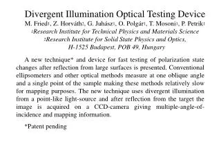
Divergent Illumination Optical Testing Device M. Fried 1 , Z. Horváth 2 , G. Juhász 1 , O. Polgár 1 , T. Mosoni 1 , P. Petrik 1 1 Research Institute for Technical Physics and Materials Science 2 Research Institute for Solid State Physics and Optics, H-1525 Budapest, POB 49, Hungary.

E N D
Divergent Illumination Optical Testing DeviceM. Fried1, Z. Horváth2, G. Juhász1, O. Polgár1, T. Mosoni1, P. Petrik11Research Institute for Technical Physics and Materials Science2Research Institute for Solid State Physics and Optics, H-1525 Budapest, POB 49, Hungary A new technique* and device for fast testing of polarization state changes after reflection from large surfaces is presented. Conventional ellipsometers and other optical methods measure at one oblique angle and a single point of the sample making these methods relatively slow for mapping purposes. The new technique uses divergent illumination from a point-like light-source and after reflection from the target the image is acquired on a CCD-camera giving multiple-angle-of-incidence and mapping information. *Patent pending
The prototype is built in the form of a wide-angle single-wavelength ellipsometer using film polarizers. The point-like source is an optical fiber coupled with a diode-laser and the elements are moved by simple stepping motors. (1) point-like source (2) light-conus (3) polarizer (4) sample on a moving stage (5) analyzer (6) CCD-camera
The axis of the light-cone is at 65o relative to the normal of the sample surface and the opening angle of the beam is more then 14 degrees, determining the range of incidence angles that can be used for measurement
With this arrangement, the angle of incidence is different for different positions of the light spot on the sample surface. Using a motorised X-Y moving stage, the sample surface can be scanned relative to the light-spot, yielding a huge amount of measured ellipsometric data (amplitude ratio – tan y and phase shift – cos D) corresponding to the different angles. Because of the linear translation one can measure the polarisation state at all the points and at every angle inside the cone. • The collected data are processed by an additional computer that provides real-time polarisation state parameter maps (and thicknesses and/or refractive indices maps) over a large area of the sample surface. The speed of the measuring system makes it suitable for use even on production lines. The amount of data and the dynamics of the CCD-detector can be optimized by grouping of the pixels.
The neccessary angle-of-incidence calibration (coupling of pixels to angles) is made via well-known and optimized structures such as silicon-silicondioxide samples. (Note edge effects caused by low intensity!)
The precision of the device is not higher than that of standard ellipsometers, but it is enough for determining the thickness of the silicondioxide film with subnanometer and the angle-of-incidence with subtenthdegree precision. (Note edge effects caused by low intensity!)
Test on a grid-like etched oxide layer (1x1 mm2 windows). One intensity picture and derived data (tan – cos "pictures"
Thickness-map of a grid-like etched oxide layer (1x1 mm2 windows). Derived from the (tan – cos "pictures"
As a demonstration, electrochemically etched porous silicon layers were made with different porosity (refractive index) and different thicknesses. Etched areas were limited by teflon O-ring causing significant edge-effects.
We made an enhancedmultiwavelength version using 3 discrete wavelengthes (different laser-diodes) at the entrance of the single optical fiber. In this case multiple-angle and spectral information can be obtained simultaneously from the surface of the sample if needed to test the complexity of the film structure.
Thickness map [nm] of the poly-Si layer of a poly-Si/SiO2/Si multi-layer structure
Thickness map [nm] of the SiO2 layer of a poly-Si/SiO2/Si multi-layer structure