Understanding the Physical Layer in Networking
470 likes | 581 Vues
Explore the fundamentals of the Physical Layer in networking, covering signal propagation, modulation schemes, latency examples, bandwidth-delay relationship, and more. Dive into the world of media properties and latency metrics.

Understanding the Physical Layer in Networking
E N D
Presentation Transcript
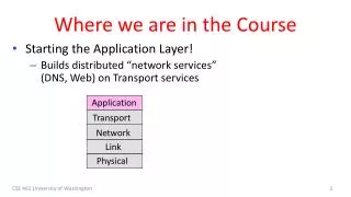
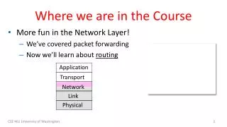
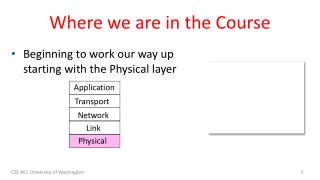
Where we are in the Course • Beginning to work our way up starting with the Physical layer Application Transport Network Link Physical CSE 461 University of Washington
Scope of the Physical Layer • Concerns how signals are used to transfer message bits over a link • Wires etc. carry analog signals • We want to send digital bits 10110… …10110 Signal CSE 461 University of Washington
Topics • Properties of media • Wires, fiber optics, wireless • Simple signal propagation • Bandwidth, attenuation, noise • Modulation schemes • Representing bits, noise • Fundamental limits • Nyquist, Shannon CSE 461 University of Washington
Simple Link Model • We’ll end with an abstraction of a physical channel • Rate (or bandwidth, capacity, speed) in bits/second • Delay in seconds, related to length • Other important properties: • Whether the channel is broadcast, and its error rate Message Delay D, Rate R CSE 461 University of Washington
Message Latency • Latency is the delay to send a message over a link • Transmission delay: time to put M-bit message “on the wire” • Propagation delay: time for bits to propagate across the wire • Combining the two terms we have: CSE 461 University of Washington
Message Latency (2) • Latency is the delay to send a message over a link • Transmission delay: time to put M-bit message “on the wire” T-delay = M (bits) / Rate (bits/sec) = M/R seconds • Propagation delay: time for bits to propagate across the wire P-delay = Length / speed of signals = Length / ⅔c = D seconds • Combining the two terms we have: L = M/R + D CSE 461 University of Washington
Metric Units • The main prefixes we use: • Use powers of 10 for rates, 2 for storage • 1 Mbps = 1,000,000 bps, 1 KB = 210bytes • “B” is for bytes, “b” is for bits CSE 461 University of Washington
Latency Examples • “Dialup” with a telephone modem: • D = 5 ms, R = 56 kbps, M = 1250 bytes • Broadband cross-country link: • D = 50 ms, R = 10 Mbps, M = 1250 bytes CSE 461 University of Washington
Latency Examples (2) • “Dialup” with a telephone modem: D = 5 ms, R = 56 kbps, M = 1250 bytes L = 5 ms+ (1250x8)/(56 x 103) sec = 184 ms! • Broadband cross-country link: D = 50 ms, R = 10 Mbps, M = 1250 bytes L = 50 ms+ (1250x8) / (10 x 106) sec = 51 ms • A long link or a slow rate means high latency • Often, one delay component dominates CSE 461 University of Washington
Bandwidth-Delay Product • Messages take space on the wire! • The amount of data in flight is the bandwidth-delay (BD) product BD = R x D • Measure in bits, or in messages • Small for LANs, big for “long fat” pipes CSE 461 University of Washington
Bandwidth-Delay Example • Fiber at home, cross-country R=40 Mbps, D=50 ms 110101000010111010101001011 CSE 461 University of Washington
Bandwidth-Delay Example (2) • Fiber at home, cross-country R=40 Mbps, D=50 ms BD = 40 x 106x 50 x 10-3 bits = 2000 Kbit = 250 KB • That’s quite a lot of data “in the network”! 110101000010111010101001011 CSE 461 University of Washington
Frequency Representation • A signal over time can be represented by its frequency components (called Fourier analysis) amplitude = Signal over time weights of harmonic frequencies CSE 461 University of Washington
Effect of Less Bandwidth • Fewer frequencies (=less bandwidth) degrades signal Lost! Bandwidth Lost! CSE 461 University of Washington Lost! 14
Signals over a Wire • What happens to a signal as it passes over a wire? • The signal is delayed (propagates at ⅔c) • The signal is attenuated (goes for m to km) • Frequencies above a cutoff are highly attenuated • Noise is added to the signal (later, causes errors) EE: Bandwidth = width of frequency band, measured in Hz CS: Bandwidth = information carrying capacity, in bits/sec CSE 461 University of Washington
Signals over a Wire (2) • Example: 2: Attenuation: Sent signal 3: Bandwidth: 4: Noise: CSE 461 University of Washington
Signals over Fiber Attenuation (dB/km • Light propagates with very low loss in three very wide frequency bands • Use a carrier to send information By SVG: Sassospicco Raster: Alexwind, CC-BY-SA-3.0, via Wikimedia Commons Wavelength (μm) CSE 461 University of Washington
Signals over Wireless • Signals transmitted on a carrier frequency, like fiber (more later) CSE 461 University of Washington
Signals over Wireless (2) • Travel at speed of light, spread out and attenuate faster than 1/dist2 Signal strength A B Distance CSE 461 University of Washington
Signals over Wireless (3) • Multiple signals on the same frequency interfere at a receiver Signal strength A B C Distance CSE 461 University of Washington
Signals over Wireless (4) • Interference leads to notion of spatial reuse(of same freq.) Signal strength A B C Distance CSE 461 University of Washington
Signals over Wireless (5) • Various other effects too! • Wireless propagation is complex, depends on environment • Some key effects are highly frequency dependent, • E.g., multipath at microwave frequencies CSE 461 University of Washington
Wireless Multipath • Signals bounce off objects and take multiple paths • Some frequencies attenuated at receiver, varies with location • Messes up signal; handled with sophisticated methods (§2.5.3) CSE 461 University of Washington
Wireless • Sender radiates signal over a region • In many directions, unlike a wire, to potentially many receivers • Nearby signals (same freq.) interfere at a receiver; need to coordinate use CSE 461 University of Washington
WiFi WiFi CSE 461 University of Washington
Wireless (2) • Microwave, e.g., 3G, and unlicensed (ISM) frequencies, e.g., WiFi, are widely used for computer networking 802.11 b/g/n 802.11a/g/n CSE 461 University of Washington
Topic • We’ve talked about signals representing bits. How, exactly? • This is the topic of modulation Signal 10110… …10110 CSE 461 University of Washington
A Simple Modulation • Let a high voltage (+V) represent a 1, and low voltage (-V) represent a 0 • This is called NRZ (Non-Return to Zero) +V Bits 0 0 1 0 1 1 1 1 0 1 0 0 0 0 1 0 -V NRZ CSE 461 University of Washington
A Simple Modulation (2) • Let a high voltage (+V) represent a 1, and low voltage (-V) represent a 0 • This is called NRZ (Non-Return to Zero) +V Bits 0 0 1 0 1 1 1 1 0 1 0 0 0 0 1 0 -V NRZ CSE 461 University of Washington
Many Other Schemes • Can use more signal levels, e.g., 4 levels is 2 bits per symbol • Practical schemes are driven by engineering considerations • E.g., clock recovery » CSE 461 University of Washington
Clock Recovery • Um, how many zeros was that? • Receiver needs frequent signal transitions to decode bits • Several possible designs • E.g., Manchester coding and scrambling (§2.5.1) 1 0 0 0 0 0 0 0 0 0 … 0 CSE 461 University of Washington
Clock Recovery – 4B/5B • Map every 4 data bits into 5 code bits without long runs of zeros • 0000 11110, 0001 01001, 1110 11100, … 1111 11101 • Has at most 3 zeros in a row • Also invert signal level on a 1 to break up long runs of 1s (called NRZI, §2.5.1) CSE 461 University of Washington
Clock Recovery – 4B/5B (2) • 4B/5B code for reference: • 000011110, 000101001, 111011100, … 111111101 • Message bits: 1 1 1 1 0 0 0 0 0 0 0 1 Coded Bits: Signal: CSE 461 University of Washington
Clock Recovery – 4B/5B (3) • 4B/5B code for reference: • 000011110, 000101001, 111011100, … 111111101 • Message bits: 1 1 1 1 0 0 0 0 0 0 0 1 1 1 1 0 1 1 1 1 1 0 0 1 0 0 1 Coded Bits: Signal: CSE 461 University of Washington
Passband Modulation • What we have seen so far is baseband modulation for wires • Signal is sent directly on a wire • These signals do not propagate well on fiber / wireless • Need to send at higher frequencies • Passband modulation carries a signal by modulating a carrier CSE 461 University of Washington
Passband Modulation (2) • Carrier is simply a signal oscillating at a desired frequency: • We can modulate it by changing: • Amplitude, frequency, or phase CSE 461 University of Washington
Passband Modulation (3) NRZ signal of bits Amplitude shift keying CSE 461 University of Washington Frequency shift keying Phase shift keying
Topic • How rapidly can we send information over a link? • Nyquist limit (~1924) » • Shannon capacity (1948) » • Practical systems are devised to approach these limits CSE 461 University of Washington
Key Channel Properties • The bandwidth (B), signal strength (S), and noise strength (N) • B limits the rate of transitions • S and N limit how many signal levels we can distinguish Bandwidth B Signal S, Noise N CSE 461 University of Washington
Nyquist Limit • The maximum symbol rate is 2B • Thus if there are V signal levels, ignoring noise, the maximum bit rate is: 1 0 1 0 1 0 1 0 1 0 1 0 1 0 1 0 1 0 1 R = 2B log2V bits/sec CSE 461 University of Washington
Claude Shannon (1916-2001) • Father of information theory • “A Mathematical Theory of Communication”, 1948 • Fundamental contributions to digital computers, security, and communications Electromechanical mouse that “solves” mazes! Credit: Courtesy MIT Museum CSE 461 University of Washington
Shannon Capacity • How many levels we can distinguish depends on S/N • Or SNR, the Signal-to-Noise Ratio • Note noise is random, hence some errors • SNR given on a log-scale in deciBels: • SNRdB = 10log10(S/N) S+N 0 N 1 2 3 CSE 461 University of Washington
Shannon Capacity (2) • Shannon limit is for capacity (C), the maximum information carrying rate of the channel: C = B log2(1 + S/N) bits/sec CSE 461 University of Washington
Wired/Wireless Perspective • Wires, and Fiber • Engineer link to have requisite SNR and B • Can fix data rate • Wireless • Given B, but SNR varies greatly, e.g., up to 60 dB! • Can’t design for worst case, must adapt data rate CSE 461 University of Washington
Wired/Wireless Perspective (2) • Wires, and Fiber • Engineer link to have requisite SNR and B • Can fix data rate • Wireless • Given B, but SNR varies greatly, e.g., up to 60 dB! • Can’t design for worst case, must adapt data rate Engineer SNR for data rate Adapt data rate to SNR CSE 461 University of Washington
Putting it all together – DSL • DSL (Digital Subscriber Line, see §2.6.3) is widely used for broadband; many variants offer 10s of Mbps • Reuses twisted pair telephone line to the home; it has up to ~2 MHz of bandwidth but uses only the lowest ~4 kHz CSE 461 University of Washington
DSL (2) • DSL uses passband modulation (called OFDM §2.5.1) • Separate bands for upstream and downstream (larger) • Modulation varies both amplitude and phase (called QAM) • High SNR, up to 15 bits/symbol, low SNR only 1 bit/symbol 0-4 kHz 26 – 138 kHz 143 kHz to 1.1 MHz Up to 12 Mbps Voice Up to 1 Mbps ADSL2: Freq. Upstream Telephone Downstream CSE 461 University of Washington