CS 838: NetFPGA Tutorial
CS 838: NetFPGA Tutorial. Theophilus Benson. Outline. Background: What is the NetFPGA? Life cycle of a packet through a NetFPGA Demo. What is the NetFPGA?. 1GE. FPGA. 1GE. 1GE. Memory. 1GE. Networking Software running on a standard PC . CPU. Memory. PCI. A hardware accelerator

CS 838: NetFPGA Tutorial
E N D
Presentation Transcript
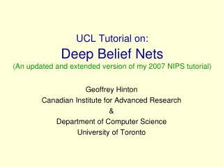
CS 838: NetFPGA Tutorial Theophilus Benson
Outline • Background: What is the NetFPGA? • Life cycle of a packet through a NetFPGA • Demo
What is the NetFPGA? 1GE FPGA 1GE 1GE Memory 1GE NetworkingSoftware running on a standard PC CPU Memory PCI A hardware accelerator built with Field Programmable Gate Arraydriving Gigabit network links
Function 4 Gigabit Ethernet ports Fully programmable FPGA hardware Open-source FPGA hardware -- Verilog base design Open-source Software -- Linux user Level Drivers in C and C++ NetFPGA Router
NetFPGA Platform Major Components • Interfaces • 4 Gigabit Ethernet Ports • PCI Host Interface • Memories • 36Mbits Static RAM • 512Mbits DDR2 Dynamic RAM • FPGA Resources • Block RAMs • Configurable Logic Block (CLBs) • Memory Mapped Registers
NetFGPA: Router Design • Pipeline of modules • FIFO queues between each module • Inter module communication • CTRL: Send on ctrl bus (8 bits) • Metadata about the data being send • DATA: Send on data bus (64 bits) • RDY: Signifies ready to receive packet (1 bit) • WR: Signifies packet being send(1bit)
Software Hardware NetFPGA Linux user-level processes Linux Processes Verilog on NetFPGA PCI board FGPA Modules 1 FGPA Modules 2
Software Hardware Example: An IP Router on NetFPGA Management & CLI Linux user-level processes Routing Protocols Exception Processing Routing Table Verilog on NetFPGA PCI board Forwarding Table Switching
Life of a Packet through the hardware 192.168.102.y 192.168.101.x port0 port2 IP packet
Router Stages MAC RxQ CPU RxQ MAC RxQ CPU RxQ MAC RxQ CPU RxQ MAC RxQ CPU RxQ Input Arbiter Output Port Lookup Output Queues MAC TxQ CPU TxQ MAC TxQ CPU TxQ MAC TxQ CPU TxQ MAC TxQ CPU TxQ
Inter-module Communication Using “Module Headers”: Ctrl Word (8 bits) Data Word (64 bits) x Module Hdr Contain information such as packet length, input port, output port, … … … y Last Module Hdr 0 Eth Hdr 0 IP Hdr 0 … 0x10 Last word of packet
Inter-module Communication Module i Module i+1 data ctrl wr rdy
MAC Rx Queue MAC Rx Queue Eth Hdr: Dst MAC = port 0, Ethertype = IP IP Hdr: IP Dst: 192.168.2.3, TTL: 64, Csum:0x3ab4 Data
Rx Queue Rx Queue 0xff Pkt length, input port = 0 0 Eth Hdr: Dst MAC = port 0, Ethertype = IP 0 IP Hdr: IP Dst: 192.168.2.3, TTL: 64, Csum:0x3ab4 0 Data
Input Arbiter Rx Q 7 Input Arbiter Pkt … Rx Q 1 Pkt Rx Q 0 Pkt
Output Port Lookup Output Port Lookup 0xff Pkt length, input port = 0 0 EthHdr: Dst MAC = 0 Src MAC = x, Ethertype = IP 0 IP Hdr: IP Dst: 192.168.2.3, TTL: 64, Csum:0x3ab4 0 Data
Output Port Lookup 5- Add output port module 1- Check input port matches Dst MAC Output Port Lookup 0x04 output port = 4 6- Modify MAC Dst and Src addresses 2- Check TTL, checksum 0xff Pkt length, input port = 0 0 EthHdr: Dst MAC = 0 Src MAC = x, Ethertype = IP EthHdr: Dst MAC = nextHopSrc MAC = port 4, Ethertype = IP 3- Lookup next hop IP & output port (LPM) 0 7-Decrement TTL and update checksum IP Hdr: IP Dst: 192.168.2.3, TTL: 64, Csum:0x3ab4 IP Hdr: IP Dst: 192.168.2.3, TTL: 63, Csum:0x3ac2 4- Lookup next hop MAC address (ARP) 0 Data
Output Queues Output Queues OQ0 OQ4 Pkt OQ7
MAC Tx Queue MAC Tx Queue 0x04 output port = 4 0xff Pkt length, input port = 0 0 EthHdr: Dst MAC = nextHopSrc MAC = port 4, Ethertype = IP 0 IP Hdr: IP Dst: 192.168.2.3, TTL: 64, Csum:0x3ab4 IP Hdr: IP Dst: 192.168.2.3, TTL: 63, Csum:0x3ac2 0 Data
MAC Tx Queue MAC Tx Queue 0x04 output port = 4 0xff Pkt length, input port = 0 0 EthHdr: Dst MAC = nextHopSrc MAC = port 4, Ethertype = IP 0 IP Hdr: IP Dst: 192.168.2.3, TTL: 64, Csum:0x3ab4 IP Hdr: IP Dst: 192.168.2.3, TTL: 63, Csum:0x3ac2 0 Data
NetFPGA-Host Interaction • Linux driver interfaces with hardware • Packet interface via standard Linux network stack • Register reads/writes via ioctl system call (with convenience wrapper functions) • readReg(nf2device *dev, int address, unsigned *rd_data) • writeReg(nf2device *dev, int address, unsigned *wr_data) eg: readReg(&nf2, OQ_NUM_PKTS_STORED_0, &val);
2. Driver performs PCI memory read/write NetFPGA-Host Interaction Register access PCI Bus 1. Software makes ioctl call on network socket. ioctl passed to driver.
NetFPGA-Host Interaction • Packet transfers shown using DMA interface • Alternative: use programmed IO to transfer packets via register reads/writes • slower but eliminates the need to deal with network sockets
DEMO: Life of a Packet through the hardware 192.168.2.y 192.168.1.x port0 port2 IP packet
Programming the FPGA with your code • nf2_download NF2/bitfiles/reference_router.bit • Mirror linux arp • ./NF2/projects/router_kit/sw/rkd • Helpful tool • ./NFlib/C/router/cli • Shows forwarding tables {arp table, ip table} • Allows to modify tables
Useful Links • NetFPGA Website • NetFPGA Wiki • NetFPGA Guide • Walkthrough the Reference Designs • The Verilog Golden Reference Guide
Hardware Description Languages • Concurrent • By Default, Verilog statements evaluated concurrently • Express fine grain parallelism • Allows gate-level parallelism • Provides Precise Description • Eliminates ambiguity about operation • Synthesizable • Generates hardware from description
Verilog Data Types reg [7:0] A; // 8-bit register, MSB to LSB // (Preferred bit order for NetFPGA) reg [0:15] B; // 16-bit register, LSB to MSB B = {A[7:0],A[0:7]}; // Assignment of bits reg [31:0] Mem [0:1023]; // 1K Word Memory integer Count; // simple signed 32-bit integer integer K[1:64]; // an array of 64 integers time Start, Stop; // Two 64-bit time variables From: CSCI 320 Computer Architecture Handbook on Verilog HDL, by Dr. Daniel C. Hyde : http://eesun.free.fr/DOC/VERILOG/verilog-manual.html
Signal Multiplexers • Two input multiplexer (using if / else) • reg y; • always @* if (select) y = a; else y = b; From: http://eesun.free.fr/DOC/VERILOG/synvlg.html Two input multiplexer (using ternary operator ?:) wire t = (select ? a : b);
Larger Multiplexers Three input multiplexer reg s; always @* begin case (select2) 2'b00: s = a; 2'b01: s = b; default: s = c; endcase end
Din D Q Dout Clock 1 Clock Transition Clock 0 time t=0 t=1 t=2 A B C Synchronous Storage Elements • Values change at times governed by clock • Clock • Input to circuit • Clock Event • Example: Rising edge Din t=0 • Flip/Flop • Transfers Value From Din to Dout on Clock event Clock Transition Dout A B S0 t=0
Synthesizable Verilog : Delay Flip/Flops • D-type flip flop • reg q; • always @ (posedge clk) q <= d; From: http://eesun.free.fr/DOC/VERILOG/synvlg.html • D type flip flop with data enable • reg q; • always @ (posedge clk) if (enable) q <= d;
NetFPGA System User Space Linux Kernel CAD Tools Monitor Software Web & VideoServer Browser & Video Client Packet Forwarding Table PCI-e PCI VI VI VI VI NIC NetFPGA RouterHardware GE GE GE GE GE GE (nf2c0 .. 3) (eth1 .. 2)
NetFPGA System Implementation • NetFPGA Blocks • Virtex-2 Pro FPGA • 4.5MB ZBT SRAM • 64MB DDR2 DRAM • PCI Host Interface • 4 Gigabit Ethernet ports • Intranet Test Ports • Dual or Quad Gigabit Etherents on PCI-e • Internet • Gigabit Ethernet on Motherboard • Processor • Dual-Core CPU • Operating System • Linux CentOS 4.4
NetFPGA Lab Setup CPU x2 Dual NIC Client Eth2 : Server PCI-e GE (eth1 .. 2) Eth1 : Local host GE Server Net-FPGA Nf2c3 : Adj. Server GE PCI NetFPGA Control SW Nf2c2 : Local Host Internet Router Hardware GE Nf2c1 : Adjacent GE Nf2c0 : Adjacent GE CAD Tools
Exception Packet • Example: TTL = 0 or TTL = 1 • Packet has to be sent to the CPU which will generate an ICMP packet as a response • Difference starts at the Output Port lookup stage
Exception Packet Path CPU RxQ CPU RxQ CPU RxQ CPU RxQ MAC TxQ MAC TxQ MAC TxQ MAC TxQ PW-OSPF Java GUI Software Driver nf2c0 nf2c1 nf2c2 nf2c3 ioctl PCI Bus DMA Registers CPU TxQ CPU TxQ CPU TxQ CPU TxQ nf2_reg_grp NetFPGA user data path MAC RxQ MAC RxQ MAC RxQ MAC RxQ Ethernet
Output Port Lookup 1- Check input port matches Dst MAC Output Port Lookup 0x04 output port = 1 2- Check TTL, checksum – EXCEPTION! 0xff Pkt length, input port = 0 0 EthHdr: Dst MAC = 0, Src MAC = x, Ethertype = IP 0 IP Hdr: IP Dst: 192.168.2.3, TTL: 1, Csum:0x3ab4 3- Add output port module 0 Data
Output Queues Output Queues OQ0 OQ1 OQ2 Pkt OQ7
CPU Tx Queue CPU Tx Queue 0x04 output port = 1 0xff Pkt length, input port = 0 0 EthHdr: Dst MAC = 0, Src MAC = x, Ethertype = IP 0 IP Hdr: IP Dst: 192.168.2.3, TTL: 64, Csum:0x3ab4 IP Hdr: IP Dst: 192.168.2.3, TTL: 1, Csum:0x3ab4 0 Data
CPU Tx Queue CPU Tx Queue 0x04 output port = 1 0xff Pkt length, input port = 0 0 EthHdr: Dst MAC = 0, Src MAC = x, Ethertype = IP 0 IP Hdr: IP Dst: 192.168.2.3, TTL: 1, Csum:0x3ab4 0 Data
ICMP Packet • For the ICMP packet, the packet arrives at the CPU Rx Queue from the PCI Bus • Follows the same path as a packet from the MAC until the Output Port Lookup. • The OPL module seeing the packet is from the CPU Rx Queue 1, sets the output port directly to 0. • The packet then continues on the same path as the non-exception packet to the Output Queues and then MAC Tx queue 0.
ICMP Packet Path CPU RxQ CPU RxQ CPU RxQ CPU RxQ MAC TxQ MAC TxQ MAC TxQ MAC TxQ PW-OSPF Java GUI Software Driver nf2c0 nf2c1 nf2c2 nf2c3 ioctl PCI Bus DMA Registers CPU TxQ CPU TxQ CPU TxQ CPU TxQ nf2_reg_grp NetFPGA user data path MAC RxQ MAC RxQ MAC RxQ MAC RxQ Ethernet
1. Packet arrives – forwarding table sends to CPU queue 2. Interrupt notifies driver of packet arrival 3. Driver sets up and initiates DMA transfer NetFPGA-Host Interaction NetFPGA to host packet transfer PCI Bus
5. Interrupt signals completion of DMA 4. NetFPGA transfers packet via DMA NetFPGA-Host Interaction NetFPGA to host packet transfer (cont) PCI Bus 6. Driver passes packet to network stack