Download
1 / 4
40 likes | 63 Vues
An optical fiber link is a part of an optic fiber communication system. Other components of the optic fiber link include the transmitter, connectors, and the receiver. The optical fiber could be single mode for long distance transmission or multi mode for short distance transmission . This paper however, majors on the impact of reflectance in the single mode optical fiber. Reflectance is a hidden threat that increases Bit Error Rate, BER, rate at which errors occur in transmission system and reduces system performance if not monitored or controlled. Optical Time Domain Reflectometer OTDR was used to measure the reflectance in single mode fiber. Events measurements in OTDR heavily depend on good reflectance. The OTDR was able to establish the reflectance in every portion of the fiber under test. An average reflectance level of 14.9275 dB of 1550 nm signal over the span length of 20.422 km was achieved which is within the acceptable standard range. Hence, good quality performance transmissions can be achieved along these routes. J. Ilouno | M. Awoji | J. Sani "Analysis on The Impact of Reflectance in Optical Fiber Links" Published in International Journal of Trend in Scientific Research and Development (ijtsrd), ISSN: 2456-6470, Volume-2 | Issue-4 , June 2018, URL: https://www.ijtsrd.com/papers/ijtsrd14378.pdf Paper URL: http://www.ijtsrd.com/physics/other/14378/analysis-on-the-impact-of-reflectance-in-optical-fiber-links/j-ilouno<br>

E N D
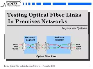
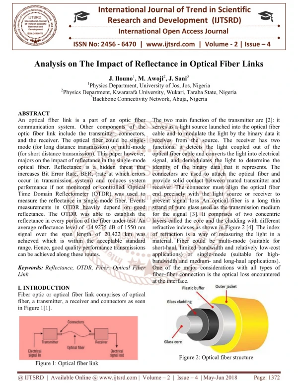
International Research Research and Development (IJTSRD) International Open Access Journal International Open Access Journal International Journal of Trend in Scientific Scientific (IJTSRD) ISSN No: 2456 - 6470 | www.ijtsrd.com | Volume ISSN No: 2456 www.ijtsrd.com | Volume - 2 | Issue – 4 Analysis on The Impact of Reflectance in Optical Fiber Links Analysis on The Impact of Reflectance in Optical Fiber Links Analysis on The Impact of Reflectance in Optical Fiber Links J. Ilouno J. Ilouno1, M. Awoji2, J. Sani3 Physics Department, University of Jos, Jos, Nigeria Physics Department, Kwararafa University, Wukari, Taraba State, Nigeria Backbone Connectivity Network, Abuja, Nigeria 1Physics Department, University of Jos, Jos, Nigeria 2Physics Department, Kwararafa University, Wukari, Taraba State, Nigeria 3Backbone Connectivity Network, Abuja, Nigeria Physics Department, Kwararafa University, Wukari, Taraba State, Nigeria The two main function of the transmitter are [2]: it serves as a light source launched into the optical fiber cable and to modulate the light by the binary data it receives from the source. The receiver has two functions: it detects the light coupled optical fiber cable and converts the light into electrical signal, and demodulates the light to determine the identity of the binary data that it represents. The connectors are used to attach the optical fiber and provide solid contact between receiver. The connector must align the optical fiber end precisely with the light source or receiver to prevent signal loss An optical fiber strand of pure glass used as the transmission medium for the signal [3]. It comprises of two concentric layers called the core and the cladding with different refractive indexes as shown in Figure 2 [4]. The index of refraction is a way of measuring the light in a material. Fiber could be multi short-haul, limited bandwidth and relatively low applications) or single-mode (suitable for high bandwidth and medium- and long One of the major considerati fiber–fiber connection is the optical loss encountered at the interface. ABSTRACT An optical fiber link is a part of an optic fiber communication system. Other components of the optic fiber link include the transmitter, connectors, and the receiver. The optical fiber could be single mode (for long distance transmission) or multi (for short distance transmission). This paper however, majors on the impact of reflectance in the single optical fiber. Reflectance is a hidden threat that increases Bit Error Rate, BER, (rate at which errors occur in transmission system) and reduces sy performance if not monitored or controlled. Optical Time Domain Reflectometer (OTDR) was used to measure the reflectance in single-mode fiber. Events measurements in OTDR heavily depend on good reflectance. The OTDR was able to establish the reflectance in every portion of the fiber under test. An average reflectance level of -14.9275 dB of 1550 nm signal over the span length of 20.422 km was achieved which is within the acceptable standard range. Hence, good quality performance transmissions can be achieved along these routes. Keywords:Reflectance, OTDR, Fiber, Optical Fiber Link I. INTRODUCTION Fiber optic or optical fiber link comprises of optical fiber, a transmitter, a receiver and connectors as seen in Figure 1[1]. An optical fiber link is a part of an optic fiber communication system. Other components of the optic fiber link include the transmitter, connectors, and the receiver. The optical fiber could be single- mode (for long distance transmission) or multi-mode or short distance transmission). This paper however, majors on the impact of reflectance in the single-mode optical fiber. Reflectance is a hidden threat that increases Bit Error Rate, BER, (rate at which errors occur in transmission system) and reduces system performance if not monitored or controlled. Optical Time Domain Reflectometer (OTDR) was used to The two main function of the transmitter are [2]: it serves as a light source launched into the optical fiber cable and to modulate the light by the binary data it receives from the source. The receiver has two functions: it detects the light coupled out of the optical fiber cable and converts the light into electrical signal, and demodulates the light to determine the identity of the binary data that it represents. The connectors are used to attach the optical fiber and provide solid contact between mated transmitter and receiver. The connector must align the optical fiber end precisely with the light source or receiver to An optical fiber is a long thin strand of pure glass used as the transmission medium for the signal [3]. It comprises of two concentric layers called the core and the cladding with different refractive indexes as shown in Figure 2 [4]. The index mode fiber. Events measurements in OTDR heavily depend on good reflectance. The OTDR was able to establish the ce in every portion of the fiber under test. An 14.9275 dB of 1550 nm signal over the span length of 20.422 km was achieved which is within the acceptable standard range. Hence, good quality performance transmissions measuring the light in a material. Fiber could be multi-mode (suitable for haul, limited bandwidth and relatively low-cost mode (suitable for high- and long-haul applications). One of the major considerations with all types of fiber connection is the optical loss encountered Reflectance, OTDR, Fiber, Optical Fiber Fiber optic or optical fiber link comprises of optical fiber, a transmitter, a receiver and connectors as seen Figure 2: Optical fiber structure Figure 2: Optical fiber structure Figure 1: Optical fiber link @ IJTSRD | Available Online @ www.ijtsrd.com @ IJTSRD | Available Online @ www.ijtsrd.com | Volume – 2 | Issue – 4 | May-Jun 2018 Jun 2018 Page: 1372
International Journal of Trend in Scientific Research and Development (IJTSRD) ISSN: 2456 International Journal of Trend in Scientific Research and Development (IJTSRD) ISSN: 2456 International Journal of Trend in Scientific Research and Development (IJTSRD) ISSN: 2456-6470 Even when the two jointed fiber ends are smooth and perpendicular to the fiber axes, and the two fiber axes are perfectly aligned, a small proportion of the light may be reflected back into the transmitting fiber causing attenuation at the joint. This phenomenon is known as Fresnel reflection and is associated with the step changes in refractive index at the jointed interface (i.e. glass–air–glass) that leads to reflectance [5].Reflectance is the amount of light reflected from a single discontinuity in an optical fiber link such as a connector pair or the percentage of light reflected by a single component [1, 2]. Reflectance is expressed as the ratio of the intensity of light reflected to the incident light intensity in dB [6]. Light traveling down the fiber when it sees a change in refractive index, then reflection (reflectance) occurs. The most common causes of reflectance may arise from air gap between the connectors and dirt or residue left behind by the cleaning solution [7]. Connectors possess different ferrule end finishes to minimize reflectance as well as loss. Reflectance of low values is obtainable from fusion splicing and from careful designed mechanical joints. mechanisms can cause larger values of reflectance. These include optical interference produced in the cavity between two fiber end faces as well as reflection from a high-index layer formed on face of a highly polished fiber. Typical reflectance measurements require a large dynamic range. Accepted reflectance values telecommunication industry vary according to the connector type as seen in Table 1 [8]: Even when the two jointed fiber ends are smooth and perpendicular to the fiber axes, and the two fiber axes igned, a small proportion of the light may be reflected back into the transmitting fiber causing attenuation at the joint. This phenomenon is known as Fresnel reflection and is associated with the step changes in refractive index at the jointed glass) that leads to reflectance [5].Reflectance is the amount of light reflected from a single discontinuity in an optical fiber link such as a connector pair or the percentage of light reflected by a An OTDR can be used in the measurements of reflectance in optical fiber. A typical OTDR consists mponents: the directional coupler, laser generator, time circuit, signal-board computer, Digital Signal Processor (DSP), and analogy to digital hold circuit, and avalanche photodiode as shown in Figure 3 [9]. An OTDR can be used in the measurements of reflectance in optical fiber. A typical OTDR consists of eight basic components: the directional coupler, laser generator, time circuit, signal Digital Signal Processor (DSP), and analogy to digital converter, sample-and-hold circuit, and avalanche photodiode as shown in Figure 3 [9]. s expressed as the ratio of the intensity of light reflected to the incident light intensity in dB [6]. Light traveling down the fiber when it sees a change in refractive index, then reflection (reflectance) occurs. The most y arise from air gap between the connectors and dirt or residue left behind by the cleaning solution [7]. Connectors possess different ferrule end finishes to minimize reflectance as well as loss. Reflectance of low values is Figure 3: Block diagra Figure 3: Block diagram of OTDR g and from careful designed mechanisms can cause larger values of reflectance. These include optical interference produced in the cavity between two fiber end faces as well as index layer formed on the end face of a highly polished fiber. Typical reflectance measurements require a large dynamic range. Accepted reflectance values telecommunication industry vary according to the mechanical joints. However, However, certain certain Figure 3 shows how light pulses are launched from the laser through the directional coupler into the optical fiber. The directional coupler channels light returned by the optical fiber to the avalanche photodiode. The avalanche photodiode then converts the light energy into electrical energy. The electrical energy is sampled at a very high rate by the sample- hold circuit. The maintains the instantaneous voltage level of each sample long enough for the analogy to digital converter to convert the electrical value to a numerical value. The numerical value from the analogy to digital converter processed by the DSP and the result is sent board computer to be stored in memory and displayed on the screen. The entire process is typically repeated many times during a single test of an optical fiber and coordinated by the timing. The OTDR will send the light constantly during certain period. The OTDR capture each sample in round–trip time means the actually transmitting time is half of what the OTDR counts. The OTDR shows the time or distance on the horizontal axis and amplitude on the vertical axis. The horizontal axis’s unit is shown in meters or kilometers, and dB (decimal) in vertical Figure 3 shows how light pulses are launched from the laser through the directional coupler into the optical fiber. The directional coupler channels light returned by the optical fiber to the avalanche photodiode. The avalanche photodiode then co the light energy into electrical energy. The electrical energy is sampled at a very high rate by the sample and-hold circuit. The maintains the instantaneous voltage level of each sample long enough for the analogy to digital converter to convert the electrical value to a numerical value. The numerical value from the analogy to digital converter processed by the DSP and the result is sent to the single-board computer to be stored in memory and displayed on the screen. The enti typically repeated many times during a single test of an optical fiber and coordinated by the timing. The OTDR will send the light constantly during certain period. The OTDR capture each sample in round time means the actually transmitti what the OTDR counts. The OTDR shows the time or distance on the horizontal axis and amplitude on the vertical axis. The horizontal axis’s unit is shown in meters or kilometers, and dB (decimal) in vertical axis. The trace generated by the OTDR can be used to identify the reflectance as seen in Figure 4. indicates high reflectance. Limits may occur to the dead zone (i.e. the distance or time where OTDR cannot detect or precisely localize event on the fiber of the OTDR. However, dead zones in in the the optical optical sample sample-and-hold circuit Table 1: Typical connectors with their reflectance Connector Type onnectors with their reflectance Typical Reflectance Typical Reflectance Flat with air -20 dB Physical Contact (PC) -30 to 40 dB 30 to 40 dB Ultra PC -40 to 50 dB 40 to 50 dB APC (angled) -60 dB or higher 60 dB or higher For laser based systems, reflectance has the capacity to reduce system performance which affects the stability of the laser source. Also, in systems with more than a connector multiple reflections occur and this increases the level of signal noise at the o detector. The specific component at fault can be identified with optical equipment such as an Optical Time Domain Reflectometor, OTDR. For laser based systems, reflectance has the capacity to reduce system performance which affects the stability of the laser source. Also, in systems with more than a connector multiple reflections occur and this increases the level of signal noise at the optical detector. The specific component at fault can be identified with optical equipment such as an Optical he OTDR can be used to identify the reflectance as seen in Figure 4. High peak Limits may occur to the (i.e. the distance or time where OTDR cannot detect or precisely localize event on the fiber) dead zones boxes that @ IJTSRD | Available Online @ www.ijtsrd.com @ IJTSRD | Available Online @ www.ijtsrd.com | Volume – 2 | Issue – 4 | May-Jun 2018 Jun 2018 Page: 1373
International Journal of Trend in Scientific Research and Development (IJTSRD) ISSN: 2456-6470 comply with TIA-455 (standard test procedures for fiber optics components) measurements to be made within the OTDR’s deadzone [7]. detected by the Avalanche photodiode receiver. The output of the photodiode receiver was driven by an integrator which improved the Signal to Noise Ratio (SNR) by giving an arithmetic average over a number of measurements at one point. This signal was fed into a logarithmic amplifier and the average measurements for successive points within the fiber were plotted and recorded with the chart recorder. The media converter was then used in converting the trace to readable format and retrieved with an external drive. The same procedure was repeated for cores 02 to 24 of the fiber and results tabulated as seen in Table 2. allow reflectance Figure 4: Reflectance Figure 4: OTDR Trace indicating Relectance II. MATERIALS & METHODS Materials: 1.Single-Mode Patch cords 2.Power meter 3.Optical Time Domain Reflectometer (OTDR) 4.Media Converter/Transmission Equipment 5.Flash drive OTDR test procedures Fiber Type: SM 96 CORE FIBER STERLITE Device: MTS 6000 Num.2487 Module: 8126LR Num.16131 The OTDR parameters were set as: Wavelength: 1550 nm Range (Km): 20.422 Acq. Time: 20s Resolution: 64cm Index: 1.46800 Figure 5: OTDR connected to fiber under test III. RESULTS Table 2: Reflectance levels Reflectance (dB) Fiber No. 1 -16.02 2 -16.92 3 -14.85 A power meter was used in testing for continuity along the cable before the measurements were taken. A single-mode patch cord was attached to the OTDR and to cable plant (core 01) under test via the patch panel at point A as shown in Figure 5. The OTDR was preset manually as stated above and it emitted light power pulses along the cable in a forward direction by the injection laser. The light pulses then bounced back and were measured by the factoring out of time and distances. The backscattered light was 4 -17.16 5 -16.83 6 -17.16 7 -17.37 8 -16.54 9 -16.41 @ IJTSRD | Available Online @ www.ijtsrd.com | Volume – 2 | Issue – 4 | May-Jun 2018 Page: 1374
International Journal of Trend in Scientific Research and Development (IJTSRD) ISSN: 2456-6470 REFERENCES 10 -17.09 1)G.P. Agrawal, Fiber-optic communication systems (New York: John Wiley & Sons ISBN 0- 47121571-6, 2002). 11 -17.14 12 17.28 2)W. Etten & J. Plaats, Fundamentals of optical fiber communications (New York: Prentice Hall, 1991). 13 -16.20 14 -17.00 3)S. Dharamvir, Optical fiber based communication network, International Journal of Technical Research (IJTR), 1 (1), 2012, 43-46. 15 -16.89 16 -16.87 4)https://www.vialite.com/resourses/guides/single- mode-vs-mult-mode/ (2018) 17 -16.88 18 -16.85 5)M. Ilyas & H.T. Moftah, Handbook of optical communication networks (Florida, USA: CRC Press, 2003). 19 -17.16 20 -14.83 6)http://questtel.com/wiki/fiber-return-loss-and- reflectance (2018) 21 -14.74 7)J.M. Senior, Optical Fiber Communications Principles and Practice, 3rd Edition (England: Pearson Practice Hall, 2009) 22 -14.61 23 -15.15 8)http://www.thefoa.org/tech/ref/testing/test/reflecta nce.html (2018) 24 -14.87 9)S.K. Raghuwanshi, Experimental characterization of fiber optic communication link for digital transmission system. Communication Technology, 5 (10), 2014, 868- 876. IV. DISCUSSION ICTACT Journal on An average reflectance level of -14.9275 dB was obtained which is within the standard specification. These small reflection events did not pose any threat or risk to the transmission capability or mechanical reliability. Therefore, it is not cost effective or advantageous to remove the fibers with these small reflection events since they have little or no impact on the fiber attenuation. The small reflection recorded might have been caused by localized changed in the refractive index of the light carrying portion of the optical fiber. However, measuring more than a 40 to 60 dB range poses a serious challenge or threat to the performance of an optical fiber link so must be technically avoided. V. CONCLUSION The impact of reflectance on single-mode fiber optics was analyzed using Reflectometer (OTDR). Small reflection events were measured and recorded as reflectance which poses no serious challenge to the system performance because their impact on the fiber attenuation was minimal or zero. Optical Time Domain @ IJTSRD | Available Online @ www.ijtsrd.com | Volume – 2 | Issue – 4 | May-Jun 2018 Page: 1375