Download
1 / 6
60 likes | 77 Vues
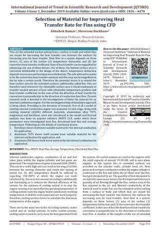
The Engine cylinder is one of the major automobile components, which is subjected to high temperature variations and thermal stresses. In order to cool the cylinder, fins are provided on the cylinder to increase the rate of heat transfer. By doing thermal analysis on the engine cylinder fins, it is helpful to know the heat dissipation inside the cylinder. The principle implemented in this project is to increase the heat dissipation rate by using the invisible working fluid, nothing but air. As know, by increasing the surface area we can increase the heat dissipation rate, so designing such a large complex engine is very difficult. The main purpose of using these cooling fins is to cool the engine cylinder by air. The main aim of the project is to analyse the thermal properties by varying geometry, material, distance between the fins and thickness of cylinder fins. Parametric models of cylinder with fins have been developed to predict the transient thermal behaviour. The models are created by varying the geometry circular and also by varying thickness of the fins for both geometries. The 3D modelling software used is Pro Engineer. Thermal analysis is done on the cylinder fins to determine variation temperature distribution over time. The analysis is done using ANSYS. Thermal analysis determines temperatures and other thermal quantities. In this thesis, using materials cast iron, Copper and Aluminium alloy 6082 are also for cylinder fin body. Thermal analysis is done using all the three materials by changing geometries, distance between the fins and thickness of the fins for the actual model of the cylinder fin body. K. Karthikeyan | C. Saravanan | Dr. T. Senthil Kumar "Enhancement of Heat Transfer Analysis and Optimization of Engine Fins of Varying Geometry" Published in International Journal of Trend in Scientific Research and Development (ijtsrd), ISSN: 2456-6470, Volume-2 | Issue-4 , June 2018, URL: https://www.ijtsrd.com/papers/ijtsrd14327.pdf Paper URL: http://www.ijtsrd.com/engineering/mechanical-engineering/14327/enhancement-of-heat-transfer-analysis-and-optimization-of-engine-fins-of-varying-geometry/k-karthikeyan<br>

E N D
International Journal of Trend in Scientific Research and Development (IJTSRD) International Open Access Journal ISSN No: 2456 - 6470 | www.ijtsrd.com | Volume - 2 | Issue – 4 Enhancement of Heat Transfer Analysis and Optimization of Engine Fins of Varying Geometry K. Karthikeyan, C. Saravanan, Dr. T. Senthil Kumar Department of Mechanical Engineering University College of Engineering, BIT Campus, Tiruchirappalii, Tamil Nadu, India ABSTRACT The Engine cylinder is one of the major automobile components, which is subjected to high temperature variations and thermal stresses. In order to cool the cylinder, fins are provided on the cylinder to increase the rate of heat transfer. By doing thermal analysis on the engine cylinder fins, it is helpful to know the heat dissipation inside the cylinder. The principle implemented in this project is to increase the heat dissipation rate by using the invisible working fluid, nothing but air. As know, by increasing the surface area we can increase the heat dissipation rate, so designing such a large complex engine is very difficult. The main purpose of using these cooling fins is to cool the engine cylinder by air. The main aim of the project is to analyse the thermal properties by varying geometry, material, distance between the fins and thickness of cylinder fins. Parametric models of cylinder with fins have been developed to predict the transient thermal behaviour. The models are created by varying the geometry circular and also by varying thickness of the fins for both geometries. The 3D modelling software used is Pro/Engineer. Thermal analysis is done on the cylinder fins to determine variation temperature distribution over time. The analysis is done using ANSYS. Thermal analysis determines temperatures and other thermal quantities. In this thesis, using materials cast iron, Copper and Aluminium alloy 6082 are also for cylinder fin body. Thermal analysis is done using all the three materials by changing geometries, distance between the fins and thickness of the fins for the actual model of the cylinder fin body. Keywords:Fin; Thermal analysis; Heat dissipation rate; Transient thermal behavior 1. INTRODUCTION The Engine cylinder is one of the major automobile components, which is subjected to high temperature variations and thermal stresses. In order to cool the cylinder, fins are provided on the cylinder to increase the rate of heat transfer. By doing thermal analysis on the engine cylinder fins, it is helpful to know the heat dissipation inside the cylinder. The principle implemented in this project is to increase the heat dissipation rate by using the invisible working fluid, nothing but air. We know that, by increasing the surface area we can increase the heat dissipation rate, so designing such a large complex engine is very difficult. The main purpose of using these cooling fins is to cool the engine cylinder by air. The main aim of the project is to analyse the thermal properties by varying geometry, material, distance between the fins and thickness of cylinder fins. Parametric models of cylinder with fins have been developed to predict the transient thermal behaviour. The models are created by varying the geometry circular and also by varying thickness of the fins for both geometries. The 3D modelling software used is Pro/Engineer. Thermal analysis is done on the cylinder fins to determine variation temperature distribution over time. The analysis is done using ANSYS. Thermal analysis determines temperatures and other thermal quantities. Copper and Aluminium alloy 6082 are also for cylinder fin body. Thermal analysis is done using all the three materials by changing geometries, distance between the fins and thickness of the fins for the actual model of the cylinder fin body. @ IJTSRD | Available Online @ www.ijtsrd.com | Volume – 2 | Issue – 4 | May-Jun 2018 Page: 1384
International Journal of Trend in Scientific Research and Development (IJTSRD) ISSN: 2456-6470 2.NATURAL AIR COOLING Useful work at the crank shaft = 25 per cent Loss to the cylinders walls = 30 per cent Loss in exhaust gases = 35 per cent Loss in friction = 10 per cent In normal cause, larger parts of an engine remain exposed to the atmospheric air. When the vehicles run, the air at certain relative velocity impinges upon the engine, and sweeps away its heat. The heat carried-away by the air is due to natural convection, therefore this method is known as natural air-cooling. Engines mounted on 2-wheelers are mostly cooled by natural air. As the heat dissipation is a function of frontal cross-sectional area of the engine, therefore there exists a need to enlarge this area. An engine with enlarge area will becomes bulky and in turn will also reduce the power by weight ratio. Hence, as an alternative arrangement, fins are constructed to enhance the frontal cross-sectional area of the engine. Fins (or ribs) are sharp projections provided on the surfaces of cylinder block and cylinder head. They increase the outer contact area between a cylinder and the air. Fins are, generally, casted integrally with the cylinder. They may also be mounted on the cylinder. Air cooled engine fin as shown in figure 2.1 It is seen that the quantity of heat given to the cylinder walls is considerable and if this heat is not removed from the cylinders it would result in the pre- ignition of the charge. In addition, the lubricant would also burn away, thereby causing the seizing of the piston. Excess heating will also damage the cylinder material. Keeping the above factors in view, it is observed that suitable means must be provided to dissipate the excess heat from the cylinder walls, so as to maintain the temperature below certain limits. However, cooling beyond optimum limits is not desirable, because it decreases the overall efficiency due to the following reasons: ➢Thermal efficiency is decreased due to more loss of heat to the cylinder walls. ➢The vaporization of fuel is less; this results in fall of combustion efficiency. ➢Low temperatures increase the viscosity of lubrication and hence more piston friction is encountered, thus decreasing the mechanical efficiency. Heat transfer rates can be increased by increasing the ➢Temperature gradient between the object and the environment ➢Convection coefficient ➢Surface Area of the object. Considering the feasibility and economical way of increasing the heat transfer rate. Extensions on the finned surfaces is used to increase the surface area of the fin in contact with the fluid flowing around it which further increases the rate of heat transfer from the base surface as compare to fin without the extensions provided to it. Types of extension provided on fin such as rectangular extensions, trapezium extensions and triangular extension. Figure 2.1 Air cooled engine fin 3.TYPESOFENGINEFINS 1) Constant area straight fin 2) Variable area straight fin 3) Pin fin 4) Radial fin 4.FINMATERIALPROPERTIES 5) Annular fin The present study is to design the engine cylinder with fins for a 150cc engine by changing the geometry such as rectangular, circular & curve shaped (parabolic) and angular fins. Table 4.1(a) show that different materials and geometry chosen for present All the heat produced by the combustion of fuel in the engine cylinders is not converted into useful power at the crankshaft. A typical distribution for the fuel energy is given below: @ IJTSRD | Available Online @ www.ijtsrd.com | Volume – 2 | Issue – 4 | May-Jun 2018 Page: 1385
International Journal of Trend in Scientific Research and Development (IJTSRD) ISSN: 2456-6470 5.PROJECTOBJECTIVE study and material properties are given in the Table 4.1(b). ➢To design fins for engine by varying the geometry such as rectangular, circular and curve shaped (parabolic) and thickness of the fins. ➢To determine the steady state temperature for the proposed fin models using design software ANSYS R14.5. Table 4.1 (a) Different materials and geometry Type of Fins Material of the fin Rectangular Aluminium Alloy 6061 The design of cooling fins is encountered in many situations and we thus examine heat transfer in a fin as a way of defining some criteria for design. Circular Aluminium Alloy 204 Angular Aluminium Alloy 2014 Curved Aluminium Alloy C443 In Internal engine combustion engines, combustion of air – fuel mixture takes place inside engine cylinder and hot gases are produced. The temperature of gases will be around 2300 – 500°C. The high temperature may result into burning of oil film between moving parts and may result into seizing or welding. Hence, this temperature must be reduced to increase the efficiency of the engine. It has been observed from the literature that the heat dissipative effects of the fins used in engine by changing geometry and material have not been reported. The present investigation work aims to investigate heat dissipative effect of fins made up of Aluminium 6061, Aluminium 2014 and Aluminium Alloy C443 and also, modifying its geometry. \ Figure 5.1.(a) Geometry of heat transfer fin A model configuration is shown in Figure 5.1(a). The fin is of length . The other parameters of the problem are indicated. The fluid has velocity and temperature. We assume (using the Reynolds analogy or other approach) that the heat transfer coefficient for the fin is known and has the value . The end of the fin can have a different heat transfer coefficient. The approach taken will be quasi-one-dimensional, in that the temperature in the fin will be assumed to be a function of only. This may seem a drastic simplification, and it needs some explanation. With a fin cross-section equal to Table 4.1 (b) Material properties and thermal conductivity Heat transfer coefficie nt (W/m²k) Thermal Conducti vity (W/mK) Densi ty (g/cc) Melting Point (K) and a perimeter P. Materials The physical content of this approximation can be seen from the following. Heat transfer per unit area out of the fin to the fluid is roughly of magnitude per unit area. The heat transfer per unit area within the fin in the transverse direction is again in the same approximate, there is a much larger capability for heat transfer per unit area across the fin than there is between the fin and the fluid, and thus little variation in temperature inside the fin in the transverse direction. To emphasize the point, consider the limiting case of zero heat transfer to the fluid, i.e., an Aluminiu m 6061 Aluminiu m 204 Aluminiu m 2014 Aluminiu m C443 167 25 2.7 855 156 25 2.75 820 160 25 2.8 780 146 25 2.69 847 @ IJTSRD | Available Online @ www.ijtsrd.com | Volume – 2 | Issue – 4 | May-Jun 2018 Page: 1386
International Journal of Trend in Scientific Research and Development (IJTSRD) ISSN: 2456-6470 insulated fin. Under these conditions, the temperature within the fin would be uniform and equal to the wall temperature. Figure 5.1 b) Element of fin showing heat transfer If there is little variation in temperature across the fin, an appropriate model is to say that the temperature within the fin is a function of only, and use a quasi- one-dimensional approach. To do this, consider an element , of the fin as shown in Figure 5.1(b). There is heat flow of magnitude at the left-hand side and heat flow out of magnitude at the right hand side. There is also heat transfer around the perimeter on the top, bottom, and sides of the fin. From a quasi-one-dimensional point of view, this is a situation similar to that with internal heat sources, but here, for a cooling fin, in each elemental slice of thickness there is essentially a heat sink of magnitude, where is the area for heat transfer to the fluid. Figure 7.1 The temperature distribution, tip temperature, and heat flux in a straight one- dimensional fin with the tip insulated. 8.DESIGN PROPERTIES The design properties are considered for the circular and rectangular fins with variable thickness like 2.5mm and 3.0mm. For the same the fin is designed using design software and analysed using ANSYS R14.5. The following diagram figure 8.1 shows the Circular fin geometry with 2.5mm thickness. Circular Fin: 6.MATERIAL SELECTION Present used material for cylinder fin body is Cast Iron. In this thesis it is replaced with Aluminum Alloy 6061.Thermal analysis is done on the cylinder body by varying the material to determine the heat transfer rate. 7.MECHANICAL PROPERTIES The standard values mechanical and thermal properties of Aluminum Alloy 6061 are taken from International Alloy Designations and Chemical Composition Limits for Wrought Aluminum Alloys. The values of various properties are found to be: 1. Melting Point: 582 - 652 °C 2. Thermal Conductivity: 167 W/m-°C 3. Specific Heat Capacity: 0.896 J/g-°C 4. Modulus of Elasticity: 68.9 GPa Fig 8.1 Circular fin geometry with 2.5mm thickness. @ IJTSRD | Available Online @ www.ijtsrd.com | Volume – 2 | Issue – 4 | May-Jun 2018 Page: 1387
International Journal of Trend in Scientific Research and Development (IJTSRD) ISSN: 2456-6470 The following diagram figure 8.2Steady state thermal analysis output for the Circular fin geometry with 2.5mm thickness. Fig 8.4 Steady state thermal analysis output for the rectangular fin geometry with 3.0mm thickness. CIRCULAR FIN RECTANGUL AR FIN STEADY STATE TEMPERAT URE Thermal Conductivity 167 W m^-1 C^-1 3.0m m 3.0m m 2.5mm 2.5mm Fig 8.2 Steady state thermal analysis output for the Circular fin geometry with 2.5mm thickness. Minnimum Temperature 957.61 °C 967.7 1 °C 970.02 °C 968.4 1°C The following diagram figure 8.3 shows the Circular fin geometry with 2.5mm thickness. Rectangular Fin: Maximum Temperature 1100° C 1100° C 1100°C 1100°C Table 8.1 Steady state temperature for circular and rectangular fin with 2.5mm and 3.0mm thickness. 9. CONCLUSION: This paper deals with the design of fins for engine by varying the geometry such as rectangular and circular and also varying the thickness of the fins like 2.5mm and 3.0mm. Using design software ANSYS R14.5 the steady state temperature for the fins are calculated and found that circular fin with 2.5mm thickness has the temperature range 957.61°C to 1100°C. This infers, the fin with 2.5mm thickness in circular geometry has high fin effectiveness and contact surface area in comparison with the 3.0mm fin thickness of the proposed circular and rectangular fins. REFERENCES 1)D. Merwin Rajesh and K Suresh Design and thermal analysis of cylinder fins by varying its geometry and material, IJME International Journal, ISSN NO: 2348- 4845 (2014) Fig 8.3 Rectangular fin geometry with 3.0mm thickness. The following diagram figure 8.4Steady state thermal analysis output for the Circular fin geometry with 3.0mm thickness. @ IJTSRD | Available Online @ www.ijtsrd.com | Volume – 2 | Issue – 4 | May-Jun 2018 Page: 1388
International Journal of Trend in Scientific Research and Development (IJTSRD) ISSN: 2456-6470 2)Salwe A. et. al (2014) ‘Comparison of Forced convective heat transfer coefficient between solid pin fin and perforated pin fin’, International Journal of Engineering Research and General Science Volume 2, Issue 3, pg: 27-32. 3)Saravanan S.V. et. al (2014) ‘Numerical Analysis and Optimization of Engine Cylinder Fins of Varying Geometry and Material’, International Journal Of Engineering Sciences & Research Technology, Vol 3, pg: 1519-1523. 4)G. Babu and M. Lavakumar (2013). "Heat Transfer Analysis and Optimization of Engine Cylinder Fins of Varying Geometry and Material." IOSR Journal of Engineering (IOSR-JMCE) 7(4): 24-29. 5)S.S.Chandrakant, et al. (2013). "Numerical and Experimental Analysis of Heat Transfer through Various Types of Fin Profiles by Forced Convection."International Journal of Engineering Research & Technology (IJERT) 2(7). 6)A.R. Kumar, et al. (2013). "Heat Transfer Analysis in the Cylinder Head of a Four-Stroke SI Engine."International Journal of Engineering Research & Technology (IJERT) 2(5). 7)R.P. Patil and P. H. M. Dange (2013). "Experimental and Dynamics Heat Transfer Analysis on Elliptical Fin by Forced Convection."International Journal of Engineering Research & Technology (IJERT) 2(8). 8)N.P.R. Rao and T. V. Vardhan (2013). "Thermal Analysis of Engine Cylinder Fins By Varying Its Geometry and Material." International Journal of Engineering 2(8). 9)S. Wange and R. Metkar (2013). "Computational Analysis of Inverted Notched Fin Arrays Dissipating Heat Convection."International Journal of Engineering and Innovative Technology (IJEIT) 2(11). 10)Krakowski R. et. al (2013) ‘Internal Combustion Engine Cooling System With Elevated Coolant Temperature Research On The Model Test Stand’, Journal of KONES Powertrain and Transport, Vol. 20, No. 4, pg: 1-8. 11)Paul A.J. et. al (2012) ‘Experimental and Parametric Study of Extended Fins In The Optimization of Internal Combustion Engine Cooling Using CFD’, International Journal of Applied Research in Mechanical Engineering, Volume-2, Issue-1, pg: 81-90. 12)Arunkumar. G | Dr. P. Navaneetha Krishnan | Dr. T. Senthil Kumar "Experimental Enhancement of Heat Transfer Analysis on Heat Pipe using SiO2 and TiO2 Nano Fluid" Published in International Journal of Trend in Scientific Research and Development (ijtsrd), ISSN: 2456-6470, Volume- 2 | Issue-4 2018,URL: http://www.ijtsrd.com/papers/ijtsrd130 94.pdf 13)Pathak Sunil, Turbo charging and oil techniques inlight motor vehicles, Res.J. Recent Sci, 1(1), 60- 65 (2012) 14)Dev Nikhil, Attri Rajesh, Mittal Vijay, Kumar Sandeep, Mohit, Satyapal, Kumar pardeep, Thermodynamic analysis of a combined heat and power system, Res.J. Recent Sci, 1(3), 76-79 (2012) 15)G.Raju, et al. (2012). "Optimal Design of an I.C. Engine Cylinder Fin Arrays Using a Binary Coded Genetic Algorithms." International Journal of Modern Engineering Research (IJMER) 2(6): 4516-4520. 16)U. Magarajan, et al. (2012). "Numerical Study on Heat Transfer of Internal Combustion Engine Cooling by Extended Fins Using CFD." International Science Congress Association 1(6): 32-37. 17)A. Mishra, et al. (2012). "Heat Transfer Augmentation of Air Cooled Internal Combustion Engine Using Fins Techniques." Research Journal of Engineering Sciences ISSN 2278:9472. 18) J.A. Paul, et al. (2012). "Experimental and Parametric Study of Extended Fins in the Optimization of Internal Combustion Engine Cooling Using CFD."International Journal of Applied Engineering (IJARME) 2(1). , June Mechanical and Civil Computational Fluid through Numerical by Natural Research in Mechanical @ IJTSRD | Available Online @ www.ijtsrd.com | Volume – 2 | Issue – 4 | May-Jun 2018 Page: 1389