Download
1 / 3
30 likes | 45 Vues
Fins are the extended surface jutting from a surface or body and which they are meant for increasing the heat transfer rate between the surfaces by increasing area for heat transfer. Heat flow in a system depends on three factors 1 area of the surface 2 temperature distinction and 3 the convective heat transfer coefficient. Rate of heat transfer can be magnified by enhancing any one of these factors. Out of these, the bottom surface area is restricted attributable to the design of the object temperature distinction depends on process and having process limitations. The sole alternative seems to be the convection heat transfer constant and this may not be magnified on the far side a certain worth. Therefore the potential choice is to extend the base surface area by the extended surfaces additionally called fins. Fins are therefore used whenever the obtainable surface area is found inadequate to transfer needed amount of heat with obtainable temperature gradient and heat transfer coefficient. In the case of fins the direction of heat transfer by convection is perpendicular to the direction of conduction heat flow. Present research work is devoted to the investigations of better fin material for an internal combustion engine. For this investigation help of simulation approach is being taken. Preceding in the direction of research, first of all a model of existing internal combustion engine was prepared. In next stage, along with existing material Al204 different materials, aluminnium alloy 7075, magnesium and beryllium, were also introduced in the model and thermal analysis was done on popular software ANSYS 15.0, under which three parameters were investigated, heat flux, directional heat flux and average temperature. Following are the details of conclusion drawn. 1. Beryllium shows itself most suitable material for the internal combustion fin application 2. Aluminum 7075 shows itself second most suitable material for the internal combustion fin application and 3. Aluminum 204 shows itself worst material for the internal combustion fin application. Abhishek Kumar | Shreeram Barkhane "Selection of Material for Improving Heat Transfer Rate for Fins using CFD" Published in International Journal of Trend in Scientific Research and Development (ijtsrd), ISSN: 2456-6470, Volume-4 | Issue-1 , December 2019, URL: https://www.ijtsrd.com/papers/ijtsrd29519.pdf Paper URL: https://www.ijtsrd.com/engineering/mechanical-engineering/29519/selection-of-material-for-improving-heat-transfer-rate-for-fins-using-cfd/abhishek-kumar<br>

E N D
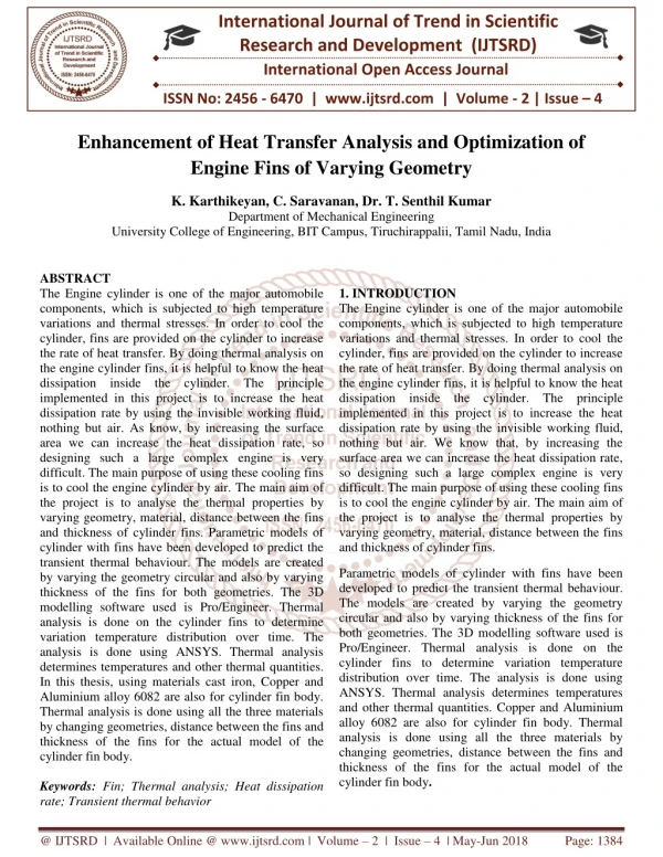
International Journal of Trend in Scientific Research and Development (IJTSRD) Volume 4 Issue 1, December 2019 Available Online: www.ijtsrd.com e-ISSN: 2456 – 6470 Selection of Material for Improving Heat Transfer Rate for Fins using CFD Abhishek Kumar1, Shreeram Barkhane2 1Assistant Professor, 2Research Scholar, 1,2KNPCST, Bhopal, Madhya Pradesh, India ABSTRACT Fins are the extended surface jutting from a surface or body and which they are meant for increasing the heat transfer rate between the surfaces by increasing area for heat transfer. Heat flow in a system depends on three factors (1) area of the surface (2) temperature distinction and (3) the convective heat transfer coefficient. Rate of heat transfer can be magnified by enhancing any one of these factors. Out of these, the bottom surface area is restricted attributable to the design of the object; temperature distinction depends on process and having process limitations. The sole alternative seems to be the convection heat transfer constant and this may not be magnified on the far side a certain worth. Therefore the potential choice is to extend the base surface area by the extended surfaces additionally called fins. Fins are therefore used whenever the obtainable surface area is found inadequate to transfer needed amount of heat with obtainable temperature gradient and heat transfer coefficient. In the case of fins the direction of heat transfer by convection is perpendicular to the direction of conduction heat flow. Present research work is devoted to the investigations of better fin material for an internal combustion engine. For this investigation help of simulation approach is being taken. Preceding in the direction of research, first of all a model of existing internal combustion engine was prepared. In next stage, along with existing material (Al204) different materials, aluminnium alloy 7075, magnesium and beryllium, were also introduced in the model and thermal analysis was done on popular software ANSYS 15.0, under which three parameters were investigated, heat flux, directional heat flux and average temperature. Following are the details of conclusion drawn. 1.Beryllium shows itself most suitable material for the internal combustion fin application; 2.Aluminum 7075 shows itself second most suitable material for the internal combustion fin application; and 3.Aluminum 204 shows itself worst material for the internal combustion fin application. KEYWORDS: Fins, ANSYS, Heat Flux, Average Temperature, Directional Heat Flux INRODUCTION Internal combustion engines, combustion of air and fuel takes place within the engine cylinder and hot gases are generated. The temperature of gases is around 2300-2500°C. This can be a really high and can result in burning of oil film between the moving elements and result into seizing of piston too. So, this temperature should be reduced to regarding 150-200°C at which the engine can work satisfactorily. An excessive amount of cooling is additionally not fascinating as it reduces the thermal efficiency of the system. So, the purpose of cooling system is to stay the engine running at its most effective operating temperature. If cooling system cools the engine below satisfactory working temperature, it shall be overcooled and not work properly; therefore, cooling system strives to maintain the minimum temperature of the engine. There are in the main two styles of cooling systems; water cooled and air cooled systems. In water cooled systems, cooling water is used to carry away the heat generated from How to cite this paper: Abhishek Kumar | Shreeram Barkhane "Selection of Material for Improving Heat Transfer Rate for Fins using CFD" Published in International Journal of Trend in Scientific Research and Development (ijtsrd), ISSN: 2456- 6470, Volume-4 | Issue-1, December 2019, pp.292-294, https://www.ijtsrd.com/papers/ijtsrd29 519.pdf Copyright © 2019 by author(s) and International Journal of Trend in Scientific Research and Development Journal. This is an Open Access article distributed under the terms of the Creative Commons Attribution License (CC (http://creativecommons.org/licenses/by /4.0) IJTSRD29519 URL: BY 4.0) the system. Air cooled systems are used in the engines with the small capacity of around 15-20 kW, and in aero plane engines. In this system fins or extended surfaces are provided on the cylinder walls, cylinder head, etc. Heat generated owing to combustion within the engine cylinder is conducted to the fins and when the air flows over the fins, heat gets dissipated by air. The quantity of heat dissipated to air depends upon many factors, but the important factors are quantity of air flowing through the fins, surface area of the fins exposed to the air, and thermal conductivity of the material used to make Fins are the extended surface jutting from a surface or body and which they are meant for increasing the heat transfer rate between the surfaces by increasing area for heat transfer. Heat flow in a system depends on three factors (1) area of the surface (2) temperature distinction and (3) the convective heat transfer coefficient. In the case of fins the direction of heat transfer by convection is perpendicular to the direction of conduction heat flow. A number of the samples of the use of extended @ IJTSRD | Unique Paper ID – IJTSRD29519 | Volume – 4 | Issue – 1 | November-December 2019 Page 292
International Journal of Trend in Scientific Research and Development (IJTSRD) @ www.ijtsrd.com eISSN: 2456-6470 surfaces are in cylinder heads of air cooled engines and compressors and on electric motor bodies. In radiators and air conditioners, tubes with circumferential fins are ordinarily accustomed increase the heat flow. Electronic chips cannot perform while not using fins to dissipate heat generated. Fins with different shapes are in use. These are (i) Plate fins of constant sectional area (ii) Plate fins of variable sectional area (iii) annular of circumferential fins with constant thickness (iv) annular fins of variable thickness (v) Pin fins with variable sectional area. Objective of the Research Following are the objectives of the research: 1.To analyze the effect of material changes on thermal characteristics of IC engine; and 2.Ranking of fin materials. LITERATURE SURVEY Chaitanya et al. (2014) The Engine cylinder is one in all the key automobile parts that is subjected to high temperature variations and thermal stresses. So as to cool down the cylinder, fins are provided on the surface of the cylinder to extend the speed of heat transfer. By doing thermal analysis on the engine cylinder fins, it is useful to understand the heat dissipation within the cylinder. We all know that, by increasing the surface area we will increase the heat dissipation rate, therefore planning such an outsized advanced engine is incredibly troublesome. The main aim of this research is to investigate the thermal properties by varied geometry, material and thickness of cylinder fins using annoys work bench. Transient thermal analysis determines temperatures and different thermal quantities that fluctuate over time. The variation of temperature distribution over time is of interest in several applications like in cooling. The correct thermal simulation may allow important design parameters to be known for improved life. Presently Material used for manufacturing cylinder f in body is aluminum Alloy A204 that has thermal conductivity of 110-150W/mk. Presently analysis is administrated for cylinder fins using this material and additionally using aluminum alloy 6061 that have higher thermal conductivities. Patel and Vora (2014) The Engine cylinder is one among the main I C Engine elements that is subjected to high temperature variations and thermal stresses. To cool down the cylinder, fins are provided on the surface of the cylinder to extend the rate of heat transfer. The main purpose of using these cooling fins is to cool down the engine cylinder by air. The main aim is that the research is to analysis thermal properties by variable geometry, material and thickness of cylinder fins. Transient thermal analysis determines temperatures and different thermal quantities that fluctuate over time. The variation of temperature distribution over time is of interest in several applications like in cooling Micheli et al. (2016) The present work analyses, for the primary time, the heat transfer from pin micro-fins. The scope of the current paper is examination thermal performance of plate micro-fin and pin micro-fin arrays underneath natural convection conditions in air. two fin geometries are considered: plate and pin fin arrays with a similar thermal exchanging surface are tested. The investigation shows that the pin micro-fins will improve the thermal performance compared to plate micro-fin arrays. Indeed, pin micro-fins are found to have higher heat transfer coefficients and lower thermal resistances, furthermore as a much better material usage. This makes pin micro-fins able to succeed each thermal enhancement and weight reduction than plate micro-fins. Patel and Meher (2015) In this research, we tend to study the variation of temperature distribution; efficiency and effectiveness of porous fin for various fractional orders α, porous parameter ξ and convection parameter δ by using Adomian Decomposition Sumudu transform method (ADSTM). Here the geometry thought-about is that rectangular porous fin and also the passage velocity in heat transfer through porous media is simulated by using Darcy’s model Bhattacharyya et al. (2017). In the present research work, the performance of an extruded finned plate air heating solar collector is studied in theory for paddy drying applications. Weather conditions and solar radiation information are accounted based on Guwahati region (26.11˚N, 91.72˚E). Outlet air temperature and pressure drop are thought of as dominant parameters to search out optimum number of fins, fin height and fin thickness. Outlet air temperature will increase so decreases with number of fins whereas pressure drop will increase with number of fins. The analysis showed that finned plate air heating solar collector with 80 fins, 0.6 Height (H) to-Duct length (D) ratio and 2 millimeter fin thickness yield best results for paddy drying applications at Guwahati weather. Cheng et al. (2015) According to the researchers, air-cooled condenser encounters risk of condense water freezing in air- cooled tube bundles in winter once environment temperature is less than ice point. This paper has concentrate on the condense water distribution and develops a condense theory model, together with condensate wall film model and condensate pool model combined with air-cooled boundary conditions for the finned flat tube with the design inclined angle of 60º. Then the inclined angle of tube is modified from 5 to 85º, and therefore the new cases are conducted. The results show that the condensation liquid film in the tube is extremely thin. At the design load, the max film situated in the pool at the end of condensation is 1.1mm, and with the inclined angle varied from 5 to 85º, the max film varied from 0.8mm to 2.1mm, which means that changing inclined angle is puny to boost anti-freezing capability. Conclusion Present research work is devoted to the investigations of better fin material for an internal combustion engine. For this investigation help of simulation approach is being taken. Preceding in the direction of research, first of all a model of existing internal combustion engine was prepared. In next stage, along with existing material (Al204) different materials, aluminum alloy 7075, magnesium and beryllium, were also introduced in the model and thermal analysis was done on popular software ANSYS 15.0, under which three parameters were investigated, heat flux, directional heat flux and average temperature. Following are the details of conclusion drawn. 1.Beryllium shows itself most suitable material for the internal combustion fin application; @ IJTSRD | Unique Paper ID – IJTSRD29519 | Volume – 4 | Issue – 1 | November-December 2019 Page 293
International Journal of Trend in Scientific Research and Development (IJTSRD) @ www.ijtsrd.com eISSN: 2456-6470 2.Aluminum 7075 shows itself second most suitable material for the internal combustion fin application; 3.Aluminum 204 shows itself worst material for the internal combustion fin application. References [1]Adegun, I. K., Jolayemi, T. S., Olayemi, O. A., & Adebisi, A. M. (2017). Numerical simulation of forced convective heat transfer in inclined elliptic ducts with multiple internal longitudinal fins. Alexandria Engineering Journal. [11]Huang, Z., Yu, G. L., Li, Z. Y., & Tao, W. Q. (2015). Numerical study on heat transfer enhancement in a receiver tube of parabolic trough solar collector with dimples, protrusions Procedia, 69, 1306-1316. and helical fins. Energy [12]Ismail, M. F., Reza, M. O., Zobaer, M. A., & Ali, M. (2013). Numerical investigation of turbulent heat convection from solid and longitudinally perforated rectangular fins. Procedia Engineering, 56, 497-502. [13]Jayachandran, B., Sajith, P. P., & Sobhan, C. B. (2015). Investigations on replacement of fins with flat heat pipes for high power LEDs. Procedia Engineering, 118, 654-661. [2]Ali, M. A., & Kherde, S. M. (2014). Design Modification And Analysis Of Two Wheeler Cooling Fins-A Review. International Journal Engineering & Technology, 7(3), 998 of Advances in [14]Laad, P., Akhare, B., & Chaurasia, P. (2016). Thermal Analysis Of Heat Sink With Fins Of Different Configuration Using International Journal Of Engineering Sciences & Research Technology, 5 (6), 82-93. [3]Bhattacharyya, T., Anandalakshmi, R., & Srinivasan, K. (2017). Heat Transfer Analysis on Finned Plate Air Heating Solar Collector for its Application in Paddy Drying. Energy Procedia, 109, 353-360. ANSYS Workbench 14.0. [15]Lee, J., Mohamed, H., & Chang, J. D. (2016). The Effect of Positions of Vertical Glass Fins inside a Double Skin Façade Air Cavity as Acoustical Barriers and Ventilation Potentials. Procedia Engineering, 145, 892- 899. [4]Chabane, F., Moummi, N., & Benramache, S. (2014). Experimental study of heat transfer and thermal performance with longitudinal fins of solar air heater. Journal of advanced research, 5(2), 183-192. [5]Chaitanya, P. S., Rani, B. S., & Kumar, K. V. (2014). Thermal Analysis of Engine Cylinder Fin by Varying Its Geometry and Material. IOSR Journal of Mechanical and Civil Engineering (IOSR-JMCE), 11, 37-44. [16]Liu, J. Q., Gu, W. B., Lu, M., Xu, H. M., & Wu, S. Z. (2014). Formation of explosively formed penetrator with fins and its flight characteristics. Defence Technology, 10(2), 119-123. [6]Cheng, T., Du, X., Yang, L., & Yang, Y. (2015). Co-current Condensation in an Inclined Air-cooled Flat Tube with Fins. Energy Procedia, 75, 3154-3161 [17]Micheli, L., Reddy, K. S., & Mallick, T. K. (2015). Plate micro-fins in natural convection: an opportunity for passive concentrating photovoltaic cooling. Energy Procedia, 82, 301-308. [7]Dhanawade, K. H., Sunnapwar, V. K., & Dhanawade, H. S. (2014). Thermal analysis of square and circular perforated fin convection. International Engineering and Technology, 2, 109-114. [18]Micheli, L., Reddy, K. S., & Mallick, T. K. (2016). Experimental comparison of micro-scaled plate-fins and pin-fins under natural convection. International Communications in Heat and Mass Transfer, 75, 59-66. arrays Journal by of forced Cultural [8]Gupta, D., & Wankhade, S. R. (2015), Design and analysis of cooling fins. IJMER), ISSN (Print), 2321-5747 [19]Micheli, L., Reddy, K. S., & Mallick, T. K. (2016). Thermal effectiveness and mass usage of horizontal micro-fins under natural convection. Applied Engineering, 97, 39-47. [9]Gupta, D., Venkataraman, V., & Nimje, R (2014). CFD & Thermal Analysis of Heat Sink and its Application in CPU. Journal of Engineering Science and Technology, 4 (8), 198-203. Thermal [20]Pal, V. (2014). Modeling and Thermal Analysis of Heat Sink with Scales on Fins Cooled by Natural Convection. International Journal of Research in Engineering and Technology. eISSN, 2319-1163. [10]Gupta, S. K., Thakur, H., & Dubey, D. (2015). Analyzing Thermal Properties of Engine Cylinder Fins by Varying Slot Size and Material. International Journal of Technology Innovations and Research, 14, 2321-1814. @ IJTSRD | Unique Paper ID – IJTSRD29519 | Volume – 4 | Issue – 1 | November-December 2019 Page 294